Service – KROHNE OPTIFLEX 2200 C_F EN User Manual
Page 102
7
SERVICE
102
OPTIFLEX 2200 C/F
www.krohne.com
07/2013 - 4000668002 - HB OPTIFLEX 2200 R02 en
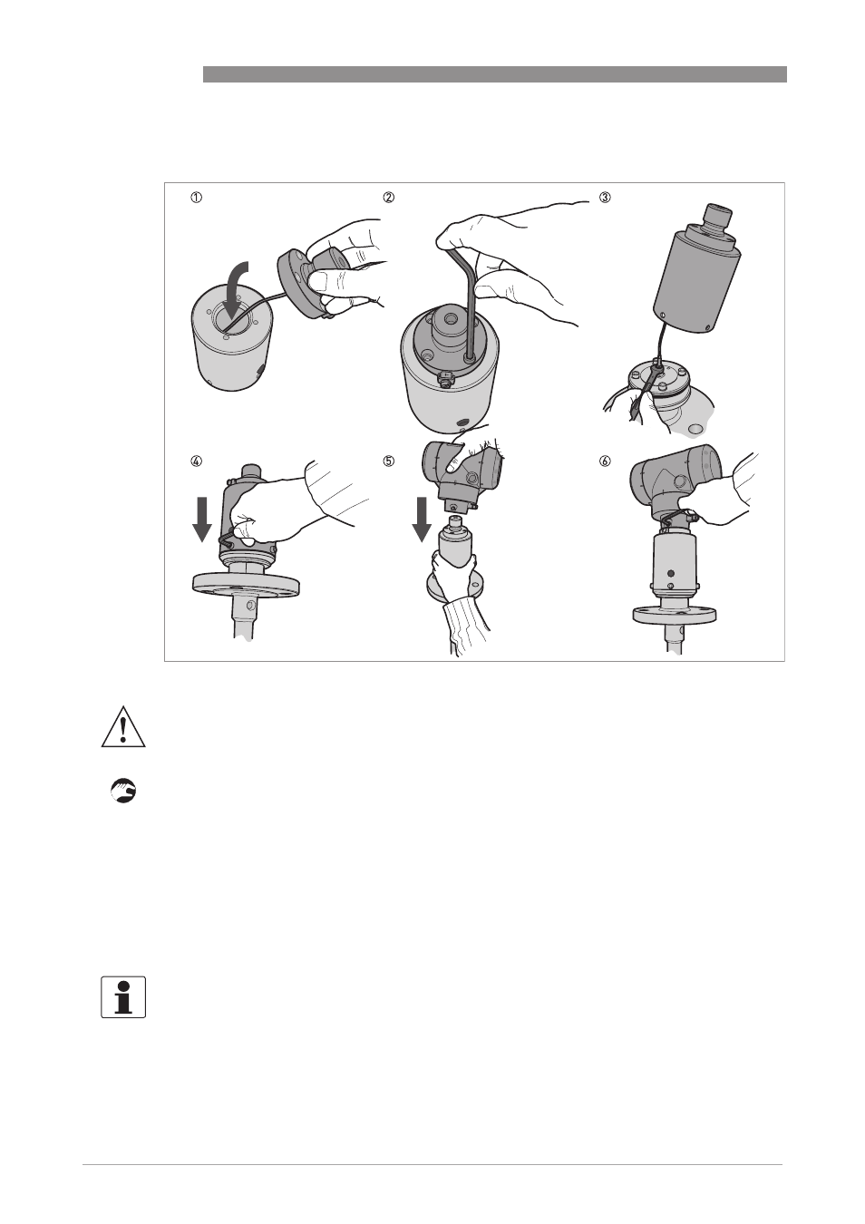
1 Attach the adaptor to the top of the isolating chamber.
2 Tighten the 4 socket head screws with a 5 mm Allen wrench.
3 Connect the 50 ohm wire connector to the process conection with an 8 mm open-end wrench.
4 Attach the isolating chamber to the process connection. The holes in the isolating chamber
must align with the holes in the process connection. Make sure that you do not damage the
50 ohm wire. Attach the 4 socket head screws at the bottom of the isolating chamber with a
5 mm Allen wrench.
5 Put the OPTIFLEX 2200 signal converter on the adaptor. Make sure that the adaptor fully en-
gages in the mating part (signal converter).
6 Tighten the socket set screw at the bottom of the signal converter with a 5 mm Allen wrench.
Procedure 3B: How to attach the OPTIFLEX 2200 signal converter (Ex-approved
devices)
Figure 7-4: Procedure 3B: How to attach the OPTIFLEX 2200 signal converter (Ex-approved devices)
WARNING!
Make sure that mating surfaces are clean. The isolating chamber must be air-tight.
INFORMATION!
The procedure that follows calibrates the new device. You must have 2 reference points (levels)
in the tank given by a different measurement solution (an approved level meter or indicator).
These points are identified as reference point 1 (R1) and reference point 2 (R2). R1 is the point
where the tank is approximately 20% full. R2 is the point where the tank is approximately 80%
full.