Installation – KROHNE OPTIFLEX 1300C EN User Manual
Page 31
INSTALLATION
3
31
OPTIFLEX 1300 C
www.krohne.com
03/2014 - 4000172306 - HB OPTIFLEX 1300 R07 en
Installation on tanks containing one liquid and foam
• The bypass chamber must have a process connection that is above the maximum level of
liquid.
• The bypass chamber must have a process connection that is below the lowest measured level
of liquid.
Installation on tanks containing more than one liquid
• The bypass chamber must have a process connection that is above the maximum level of
liquid.
• The bypass chamber must have a process connection that is below the lowest measured level
of liquid.
• There must be more process connections along the length of the bypass chamber. These
must have a minimum diameter of 25 mm / 1¨ with a minimum distance of 100 mm / 4¨
between the holes.
• If the probe has a counterweight, make sure that there is enough space between the
counterweight and the wall of the stilling well.
• If the interface liquid does not have a layer of air above it, fit a vent at the top of the bypass
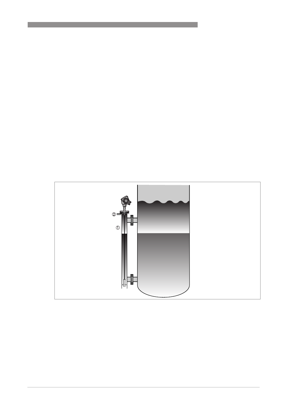
chamber. Refer to the illustration that follows:
Figure 3-21: Installation recommendations for bypass chambers with no air gap
1 Bypass chamber with no air gap
2 Air vent