Micromod Micro-DCI: 53MC5000 Training Manual User Manual
Page 142
Training Manual
F-CIM Lab
9 - 28
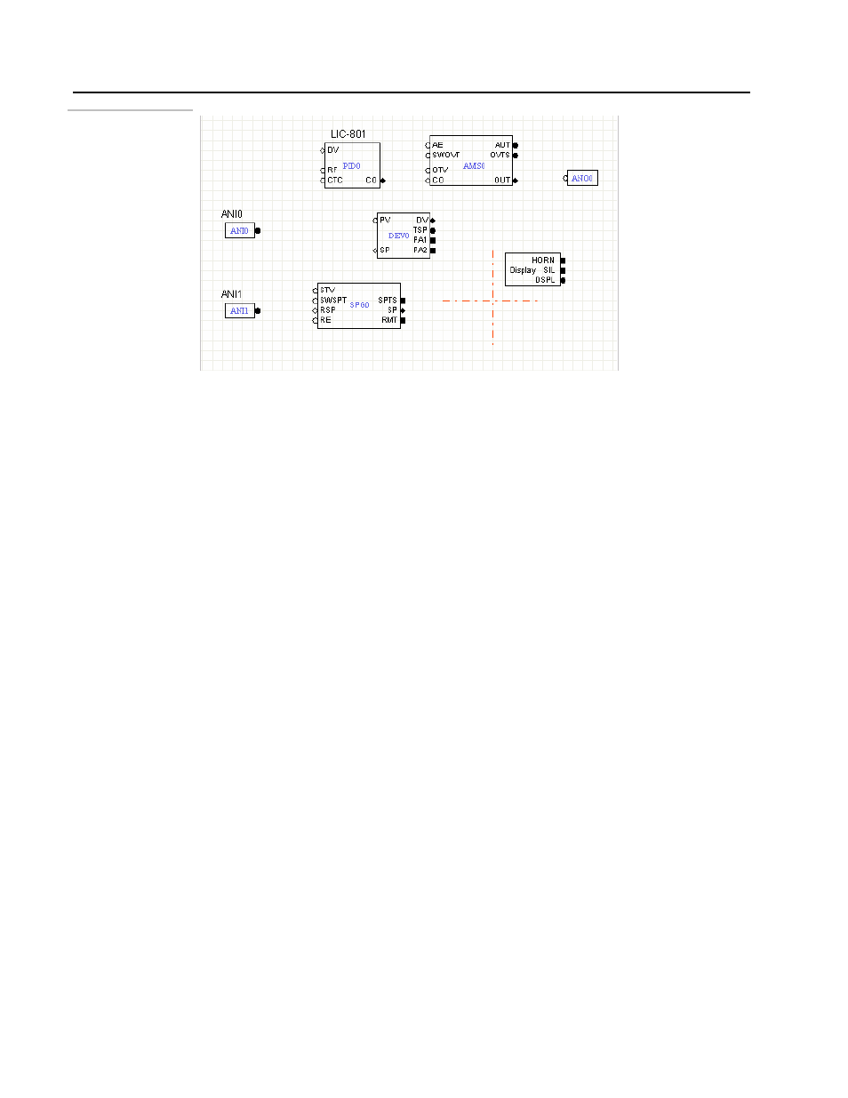
Figure 9.27.
Blocks in the F-CIM
Editor
5.
Connect the blocks: Our next step is to link the modules together to form a working
control application.
#
You will notice that the modules have inputs on the left side of the module and outputs
on the right side. Inputs are further identified as empty or hollow squares, circles or
diamonds, Outputs are filled squares, circles or diamonds. The circles and squares also
have meaning. Circles represent analog or floating point type signals while squares
represent discrete or logical type signals.
What remains to do is link the modules together to form the final control strategy.
Linking the modules requires drawing a line from the output of one module to the input on
the next module. The squares, circles and diamonds are an aid in keeping these
connections correct, discrete connects to discrete, analog connects to analog.
• From the tool bar, select the Signal wire tool. This is the tool that looks like a
black diagonal line with a black dot at each end.
• Select this tool with a left click. The tool is selected when the tool is outlined in
red. Begin by connecting the output of ANI0 module with the PV of the DEV
module.
• Use the mouse to left click on the output circle of the module. Drag the mouse to
the PV input circle on the DEV module and let click the mouse again.
• Micro-Tools will draw the connecting line.