Micromod Micro-DCI: 53MC5000 Training Manual User Manual
Page 138
Training Manual
F-CIM Lab
9 - 24
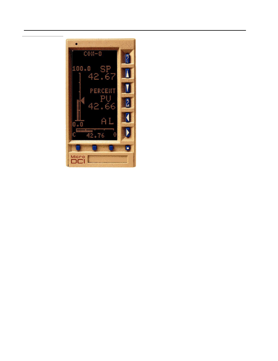
Figure 9.22.
FCIM RUNNING
13.
Test the program: It is time to test your program now. Review the requirements as in step
1.
• Make sure that the control mode is AUTO. The letter A should be displayed just
above the Output bargraph (horizontal) at the bottom as shown in the figure above.
• Note the value of the setpoint. It should be same as the value of the output because
we configured the output to track the setpoint in Auto mode.
• Press the A/M button to put the control loop in Manual Mode. The letter M will
be displayed just above the Output bargraph (horizontal) at the bottom.
• Increase or decrease the value of the output using the LEFT/RIGHT keys. It should
be different from the setpoint value.
• Put the control mode back in AUTO mode by pressing the A/M button. Watch the
output value changing automatically to match the setpoint value.
#
You an also test the program by closing the contact input 1. This should enable Output
tracking. The tracking signal will be read from the Analog Input 2. The other
requirements were:
• Enable Setpoint tracking of Process Variable when the controller is not in Auto
mode. We will assume that the PV comes from Analog input 0
• Disable Remote setpoint on closure of Contact input 0. We will assume that the
remote setpoint input comes from Analog Input 1.