Interference – Ocean Optics NanoCalc User Manual
Page 72
Ocean Optics Germany GmbH Thin Film Metrology
71
153,1.5477,0
n and k at 153 nm
154,1.5464,0
n and k at 154 nm
and so on......
The first lines are not used by the software for calculation.
ATTENTION: Do not use any blanks in the name of the file !
The third line (150,900) means that measured data are measured (=available) between these limits
(LowerLimit=150 nm and UpperLimit=900 nm) and all extracted and displayed data (drawn in light Grey
instead of black) between 900-1100 nm have NO meaning !!
11.3
Interference
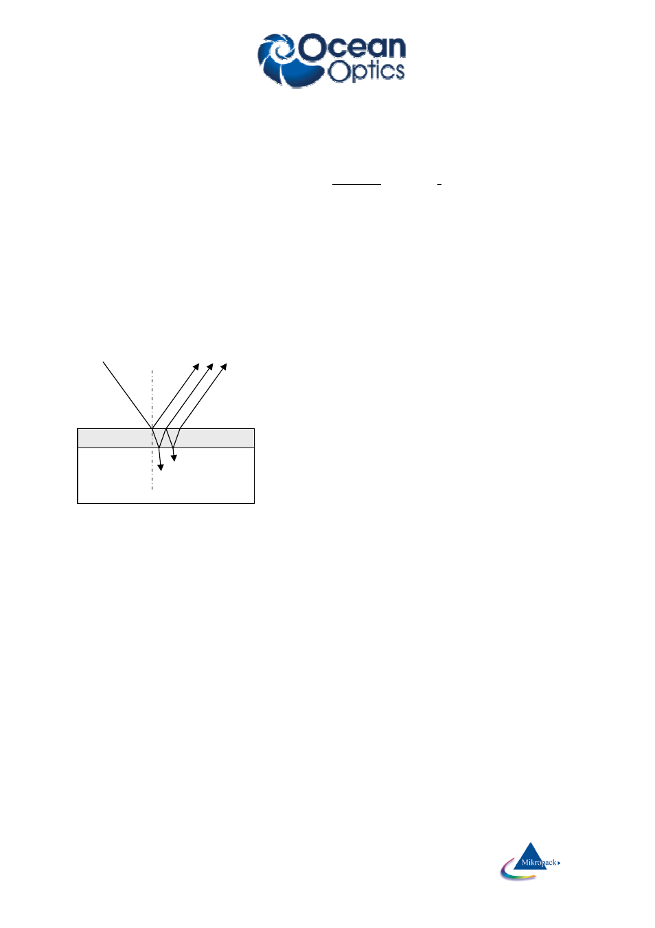
The arrangement in the picture below shows the case of an oblique incidence (just to explain „angle of
incidence“) in contrast to usual experimental setup of a vertical incidence.
The measurement of reflectivity of thin films is a good example of an interference problem:
The incoming wave splits up in a reflected and a transmitted wave at each external or internal surface. The
amplitudes of these partial waves depend on:
1.angle of incidence (if this angle is >0, then polarization
plays an important role)
2.refraction index and absorption index of all layers
Now the superposition of ALL waves (with different phase
relations, amplitudes) has to be done. If the layers are thin
and flat you have to add amplitudes and not intensities
(see your physics text book). So you may end up with
„destructive and constructive interference“: a positive
amplitude and a negative amplitude may add up to zero.
This is why your measured intensities usually have maxima
and minima.
layer
substrate
reflected intsity
incident intensity
transmitted (and
absorbed) intensity