2 disabling, 3 frame format, 4 parity bit calculation – Rainbow Electronics ATtiny10 User Manual
Page 98: 5 supported characters
98
8127B–AVR–08/09
ATtiny4/5/9/10
14.3.2
Disabling
Provided that the NVM enable bit has been cleared, the TPI is automatically disabled if the
RESET pin is released to inactive high state or, alternatively, if V
HV
is no longer applied to the
RESET pin.
If the NVM enable bit is not cleared a power down is required to exit TPI programming mode.
See NVMEN bit in
“TPISR – Tiny Programming Interface Status Register” on page 106
14.3.3
Frame Format
The TPI physical layer supports a fixed frame format. A frame consists of one character, eight
bits in length, and one start bit, a parity bit and two stop bits. Data is transferred with the least
significant bit first.
Figure 14-4. Serial frame format.
Symbols used in
ST:
Start bit (always low)
D0-D7: Data bits (least significant bit sent first)
P:
Parity bit (using even parity)
SP1:
Stop bit 1 (always high)
SP2:
Stop bit 2 (always high)
14.3.4
Parity Bit Calculation
The parity bit is always calculated using even parity. The value of the bit is calculated by doing
an exclusive-or of all the data bits, as follows:
P = D0
⊗
D1
⊗
D2
⊗
D3
⊗
D4
⊗
D5
⊗
D6
⊗
D7
⊗
0
where:
P:
Parity bit using even parity
D0-D7:
Data bits of the character
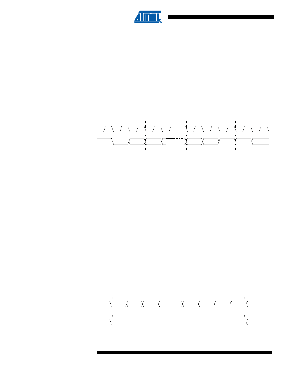
14.3.5
Supported Characters
The BREAK character is equal to a 12 bit long low level. It can be extended beyond a bit-length
of 12.
Figure 14-5. Supported characters.
TPIDATA
TPICLK
SP1
ST
SP2
IDLE/ST
IDLE
P
D1
D0
D7
IDLE/ST
IDLE
BREAK CHARACTER
DATA CHARACTER
SP1
ST
SP2
IDLE/ST
IDLE
P
D1
D0
D7
TPIDATA
TPIDATA