Power management and sleep modes, 1 sleep modes, 1 idle mode – Rainbow Electronics ATtiny10 User Manual
Page 23
23
8127B–AVR–08/09
ATtiny4/5/9/10
7.
Power Management and Sleep Modes
The high performance and industry leading code efficiency makes the AVR microcontrollers an
ideal choise for low power applications. In addition, sleep modes enable the application to shut
down unused modules in the MCU, thereby saving power. The AVR provides various sleep
modes allowing the user to tailor the power consumption to the application’s requirements.
7.1
Sleep Modes
Figure 6-1 on page 17
presents the different clock systems and their distribution in
ATtiny4/5/9/10. The figure is helpful in selecting an appropriate sleep mode.
the different sleep modes and their wake up sources.
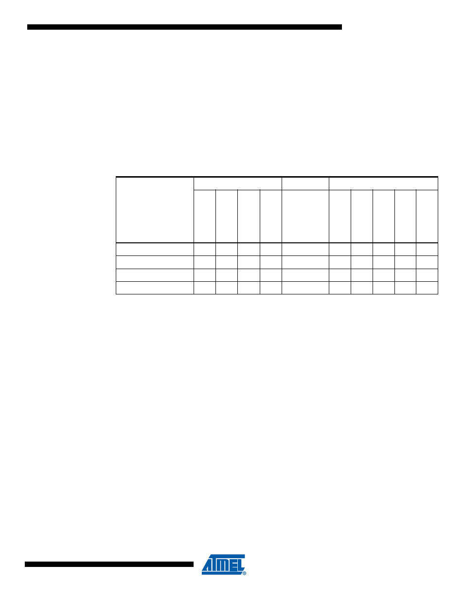
Note:
1. The ADC is available in ATtiny5/10, only
2. For INT0, only level interrupt.
To enter any of the four sleep modes, the SE bits in SMCR must be written to logic one and a
SLEEP instruction must be executed. The SM2:0 bits in the SMCR register select which sleep
mode (Idle, ADC Noise Reduction, Standby or Power-down) will be activated by the SLEEP
instruction. See
Table 7-2
for a summary.
If an enabled interrupt occurs while the MCU is in a sleep mode, the MCU wakes up. The MCU
is then halted for four cycles in addition to the start-up time, executes the interrupt routine, and
resumes execution from the instruction following SLEEP. The contents of the Register File and
SRAM are unaltered when the device wakes up from sleep. If a reset occurs during sleep mode,
the MCU wakes up and executes from the Reset Vector.
Note that if a level triggered interrupt is used for wake-up the changed level must be held for
some time to wake up the MCU (and for the MCU to enter the interrupt service routine). See
“External Interrupts” on page 36
for details.
7.1.1
Idle Mode
When bits SM2:0 are written to 000, the SLEEP instruction makes the MCU enter Idle mode,
stopping the CPU but allowing the analog comparator, timer/counter, watchdog, and the inter-
rupt system to continue operating. This sleep mode basically halts clk
CPU
and clk
NVM
, while
allowing the other clocks to run.
Idle mode enables the MCU to wake up from external triggered interrupts as well as internal
ones like the timer overflow. If wake-up from the analog comparator interrupt is not required, the
Table 7-1.
Active Clock Domains and Wake-up Sources in Different Sleep Modes
Sleep Mode
Active Clock Domains
Oscillators
Wake-up Sources
clk
CPU
clk
NVM
clk
IO
clk
ADC
Mai
n
Cloc
k
So
urce Enab
le
d
INT0 and
Pi
n C
han
ge
ADC
Other I/O
W
a
tchdog
Interr
upt
VLM
Interr
upt
Idle
X
X
X
X
X
X
X
X
ADC Noise Reduction
X
X
X
(2)
X
X
X
Standby
X
X
(2)
X
Power-down
X
(2)
X