16-bit timer/counter0, 1 features, 2 overview – Rainbow Electronics ATtiny10 User Manual
Page 52
52
8127B–AVR–08/09
ATtiny4/5/9/10
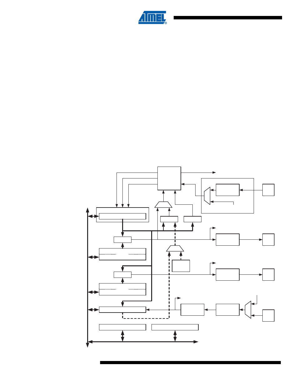
11. 16-bit Timer/Counter0
11.1
Features
•
True 16-bit Design, Including 16-bit PWM
•
Two Independent Output Compare Units
•
Double Buffered Output Compare Registers
•
One Input Capture Unit
•
Input Capture Noise Canceler
•
Clear Timer on Compare Match (Auto Reload)
•
Glitch-free, Phase Correct Pulse Width Modulator (PWM)
•
Variable PWM Period
•
Frequency Generator
•
External Event Counter
•
Four independent interrupt Sources (TOV0, OCF0A, OCF0B, and ICF0)
11.2
Overview
The 16-bit Timer/Counter unit allows accurate program execution timing (event management),
wave generation, and signal timing measurement.
Figure 11-1. 16-bit Timer/Counter Block Diagram
Clock Select
Timer/Counter
D
ATA
B
U
S
OCRnA
OCRnB
ICRn
=
=
TCNTn
Waveform
Generation
Waveform
Generation
OCnA
OCnB
Noise
Canceler
ICPn
=
Fixed
TOP
Values
Edge
Detector
Control Logic
=
0
TOP
BOTTOM
Count
Clear
Direction
TOVn
(Int.Req.)
OCnA
(Int.Req.)
OCnB
(Int.Req.)
ICFn (Int.Req.)
TCCRnA
TCCRnB
( From Analog
Comparator Ouput )
Tn
Edge
Detector
( From Prescaler )
clk
Tn