5 digital input enable and sleep modes, 6 unconnected pins, Fer to the section – Rainbow Electronics ATtiny10 User Manual
Page 44: Digital, For d
44
8127B–AVR–08/09
ATtiny4/5/9/10
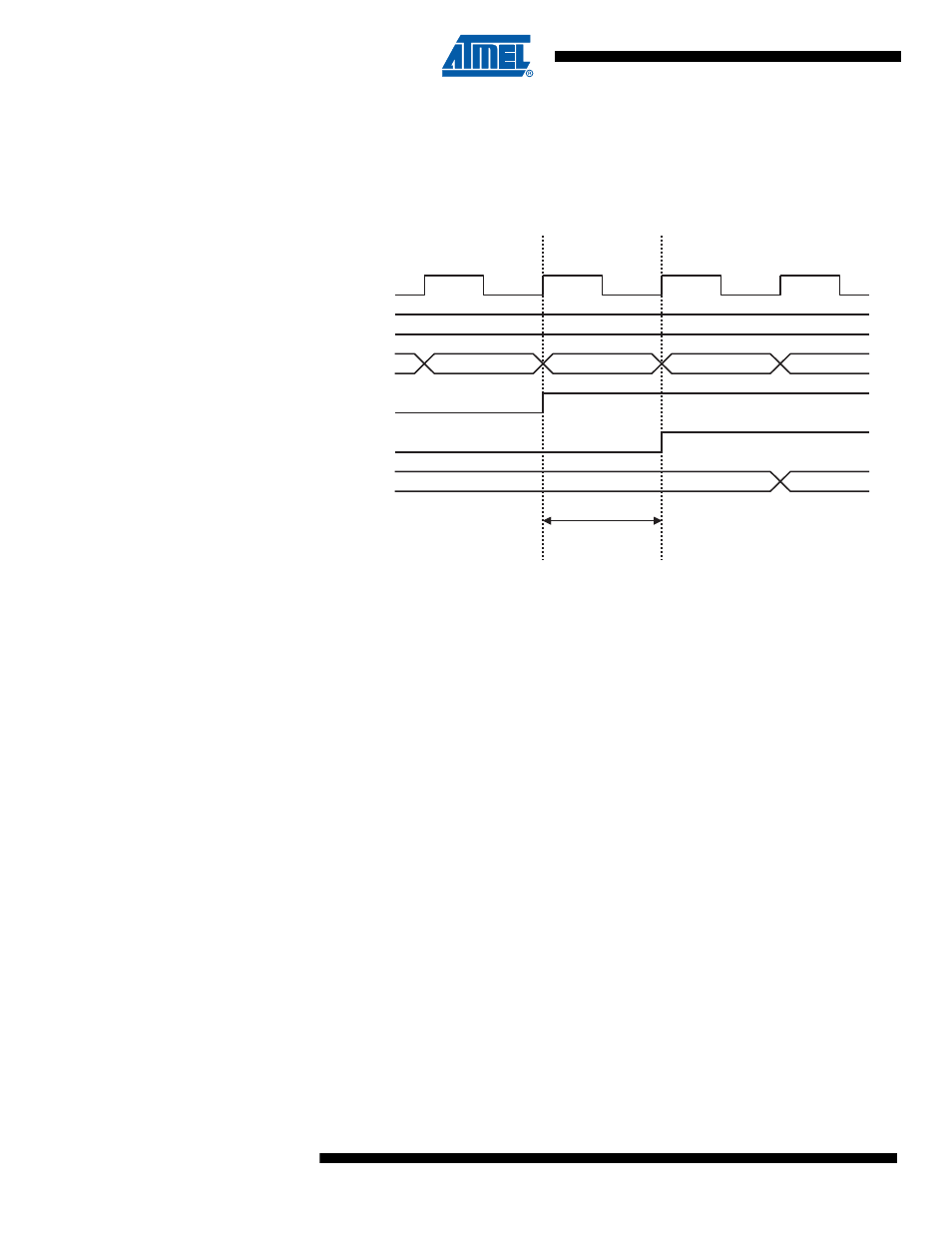
When reading back a software assigned pin value, a nop instruction must be inserted as indi-
cated in
Figure 10-5 on page 44
. The out instruction sets the “SYNC LATCH” signal at the
positive edge of the clock. In this case, the delay tpd through the synchronizer is one system
clock period.
Figure 10-5. Synchronization when Reading a Software Assigned Pin Value
10.2.5
Digital Input Enable and Sleep Modes
As shown in
Figure 10-2 on page 41
, the digital input signal can be clamped to ground at the
input of the schmitt-trigger. The signal denoted SLEEP in the figure, is set by the MCU Sleep
Controller in Power-down and Standby modes to avoid high power consumption if some input
signals are left floating, or have an analog signal level close to V
CC
/2.
SLEEP is overridden for port pins enabled as external interrupt pins. If the external interrupt
request is not enabled, SLEEP is active also for these pins. SLEEP is also overridden by various
other alternate functions as described in
“Alternate Port Functions” on page 45
If a logic high level (“one”) is present on an asynchronous external interrupt pin configured as
“Interrupt on Rising Edge, Falling Edge, or Any Logic Change on Pin” while the external interrupt
is not enabled, the corresponding External Interrupt Flag will be set when resuming from the
above mentioned Sleep mode, as the clamping in these sleep mode produces the requested
logic change.
10.2.6
Unconnected Pins
If some pins are unused, it is recommended to ensure that these pins have a defined level. Even
though most of the digital inputs are disabled in the deep sleep modes as described above, float-
ing inputs should be avoided to reduce current consumption in all other modes where the digital
inputs are enabled (Reset, Active mode and Idle mode).
The simplest method to ensure a defined level of an unused pin, is to enable the internal pull-up.
In this case, the pull-up will be disabled during reset. If low power consumption during reset is
important, it is recommended to use an external pull-up or pulldown. Connecting unused pins
directly to V
CC
or GND is not recommended, since this may cause excessive currents if the pin is
accidentally configured as an output.
out PORTx, r16
nop
in r17, PINx
0xFF
0x00
0xFF
SYSTEM CLK
r16
INSTRUCTIONS
SYNC LATCH
PINxn
r17
t
pd