Vlmcsr – Rainbow Electronics ATtiny10 User Manual
Page 33
33
8127B–AVR–08/09
ATtiny4/5/9/10
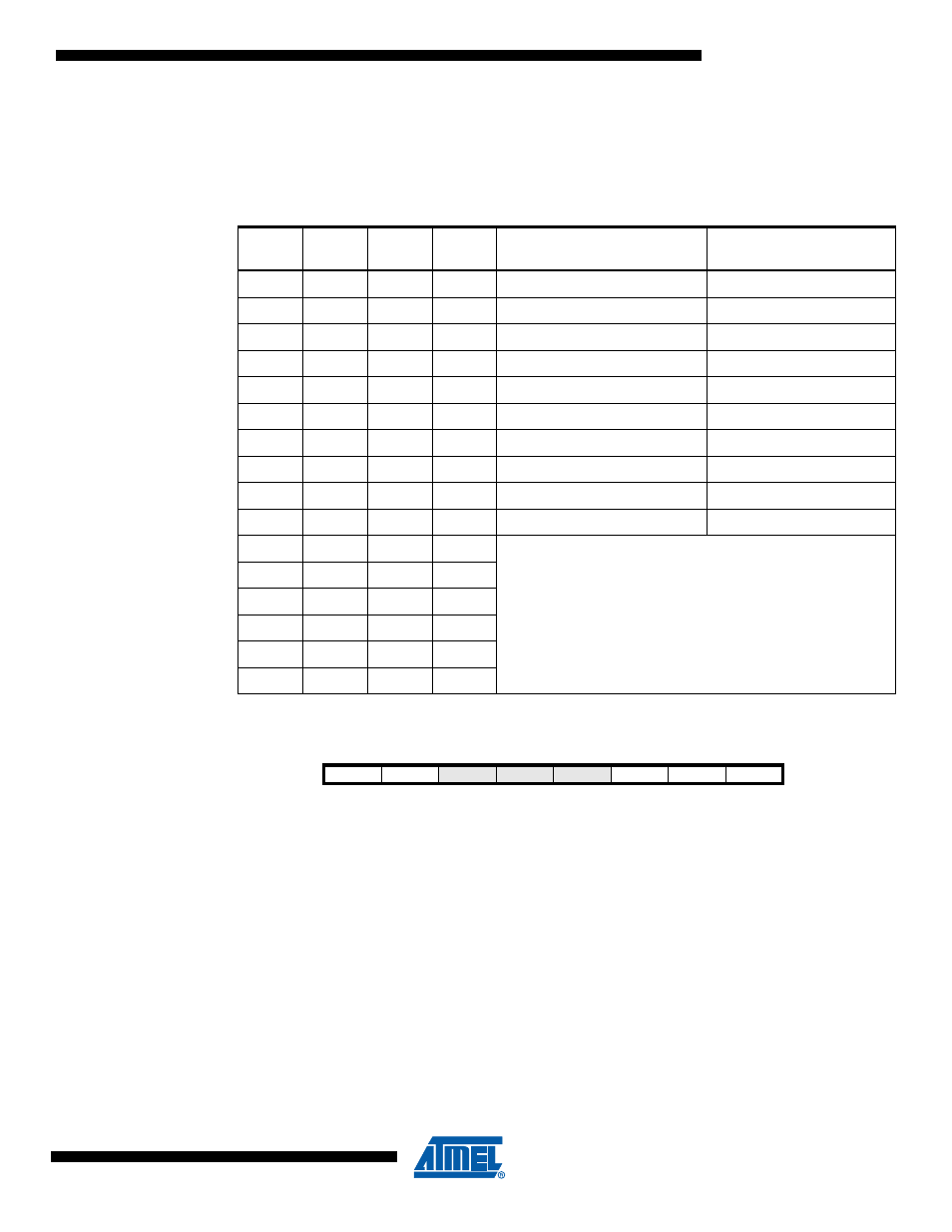
• Bits 5, 2:0 – WDP3..0: Watchdog Timer Prescaler 3, 2, 1 and 0
The WDP3..0 bits determine the Watchdog Timer prescaling when the Watchdog Timer is run-
ning. The different prescaling values and their corresponding time-out periods are shown in
Table 8-3 on page 33
.
8.4.2
VLMCSR – V
CC
Level Monitoring Control and Status register
• Bit 7 – VLMF: VLM Flag
This bit is set by the VLM circuit to indicate that a voltage level condition has been triggered (see
Table 8-4
). The bit is cleared when the trigger level selection is set to “Disabled”, or when volt-
age at V
CC
rises above the selected trigger level.
• Bit 6 – VLMIE: VLM Interrupt Enable
When this bit is set the VLM interrupt is enabled. A VLM interrupt is generated every time the
VLMF flag is set.
• Bits 5:3 – Res: Reserved Bits
These bits are reserved. For ensuring compatibility with future devices, these bits must be writ-
ten to zero, when the register is written.
Table 8-3.
Watchdog Timer Prescale Select
WDP3
WDP2
WDP1
WDP0
Number of WDT
Oscillator Cycles
Typical Time-out at
V
CC
= 5.0V
0
0
0
0
2K (2048) cycles
16 ms
0
0
0
1
4K (4096) cycles
32 ms
0
0
1
0
8K (8192) cycles
64 ms
0
0
1
1
16K (16384) cycles
0.125 s
0
1
0
0
32K (32768) cycles
0.25 s
0
1
0
1
64K (65536) cycles
0.5 s
0
1
1
0
128K (131072) cycles
1.0 s
0
1
1
1
256K (262144) cycles
2.0 s
1
0
0
0
512K (524288) cycles
4.0 s
1
0
0
1
1024K (1048576) cycles
8.0 s
1
0
1
0
Reserved
1
0
1
1
1
1
0
0
1
1
0
1
1
1
1
0
1
1
1
1
Bit
7
6
5
4
3
2
1
0
VLMF
VLMIE
–
–
–
VLM2
VLM1
VLM0
VLMCSR
Read/Write
R
R/W
R
R
R
R
R/W
R/W
Initial Value
0
0
0
0
0
0
0
0