4 register description, 1 portcr – port control register, 2 pueb – port b pull-up enable control register – Rainbow Electronics ATtiny10 User Manual
Page 50: Ils, see, Relate the a
50
8127B–AVR–08/09
ATtiny4/5/9/10
Notes:
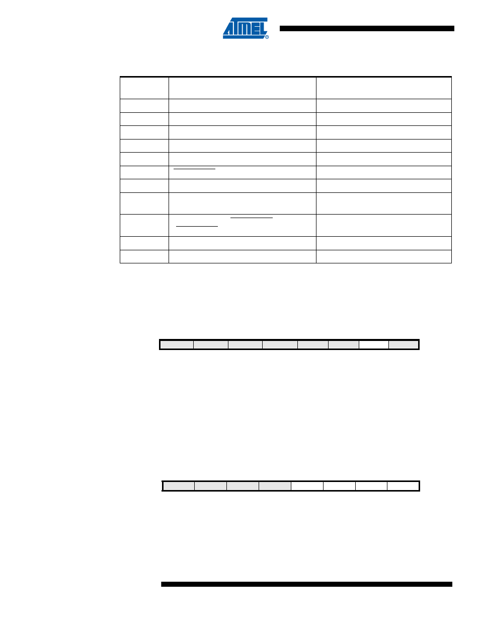
1. EXT_CLOCK is 1 when external clock is selected as main clock.
10.4
Register Description
10.4.1
PORTCR – Port Control Register
• Bits 7:2, 0 – Reserved
These bits are reserved and will always read zero.
• Bit 1 – BBMB: Break-Before-Make Mode Enable
When this bit is set the Break-Before-Make mode is activated for the entire Port B. The interme-
diate tri-state cycle is then inserted when writing DDRxn to make an output. For further
information, see
“Break-Before-Make Switching” on page 42
.
10.4.2
PUEB – Port B Pull-up Enable Control Register
Table 10-5.
Overriding Signals for Alternate Functions in PB1..PB0
Signal
Name
PB1/ADC1/AIN1/OC0B/CLKI/ICP0/PCINT1
PB0/ADC0/AIN0/OC0A/PCINT0
PUOE
0
PUOV
0
0
DDOE
EXT_CLOCK
0
DDOV
0
0
PVOE
+ OC0B Enable
OC0A Enable
PVOV
• OC0B
OC0A
PTOE
0
0
DIEOE
+ (PCINT1 • PCIE0) +
ADC1D
(PCINT0 • PCIE0) + ADC0D
DIEOV
• PWR_DOWN) +
• PCINT1 • PCIE0)
PCINT0 • PCIE0
DI
CLOCK/ICP0/PCINT1 Input
PCINT0 Input
AIO
ADC1/Analog Comparator Negative Input
ADC0/Analog Comparator Positive Input
Bit
7
6
5
4
3
2
1
0
0x03
–
–
–
–
–
–
BBMB
–
PORTCR
Read/Write
R
R
R
R
R
R
R/W
R
Initial Value
0
0
0
0
0
0
0
0
Bit
7
6
5
4
3
2
1
0
0x03
–
–
–
–
PUEB3
PUEB2
PUEB1
PUEB0
PUEB
Read/Write
R
R
R
R
R/W
R/W
R/W
R/W
Initial Value
0
0
0
0
0
0
0
0