System control and reset, 1 resetting the avr, 2 reset sources – Rainbow Electronics ATtiny10 User Manual
Page 27
27
8127B–AVR–08/09
ATtiny4/5/9/10
8.
System Control and Reset
8.1
Resetting the AVR
During reset, all I/O registers are set to their initial values, and the program starts execution from
the Reset Vector. The instruction placed at the Reset Vector must be a RJMP – Relative Jump –
instruction to the reset handling routine. If the program never enables an interrupt source, the
interrupt vectors are not used, and regular program code can be placed at these locations. The
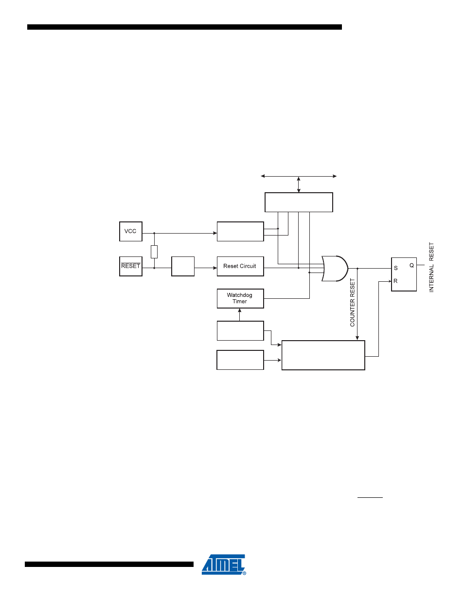
circuit diagram in
Figure 8-1
shows the reset logic. Electrical parameters of the reset circuitry are
defined in section
“System and Reset Characteristics” on page 119
.
Figure 8-1.
Reset Logic
The I/O ports of the AVR are immediately reset to their initial state when a reset source goes
active. This does not require any clock source to be running.
After all reset sources have gone inactive, a delay counter is invoked, stretching the internal
reset. This allows the power to reach a stable level before normal operation starts. The start up
sequence is described in
“Starting from Reset” on page 20
.
8.2
Reset Sources
The ATtiny4/5/9/10 have three sources of reset:
• Power-on Reset. The MCU is reset when the supply voltage is below the Power-on Reset
threshold (V
POT
)
• External Reset. The MCU is reset when a low level is present on the RESET pin for longer
than the minimum pulse length
• Watchdog Reset. The MCU is reset when the Watchdog Timer period expires and the
Watchdog is enabled
Reset Flag Register
(RSTFLR)
Delay Counters
CK
TIMEOUT
WDRF
EX
TRF
PORF
VLMRF
DATA BUS
Clock
Generator
SPIKE
FILTER
Pull-up Resistor
Watchdog
Oscillator
Power-on Reset
Circuit