3 rstflr – reset flag register – Rainbow Electronics ATtiny10 User Manual
Page 34
34
8127B–AVR–08/09
ATtiny4/5/9/10
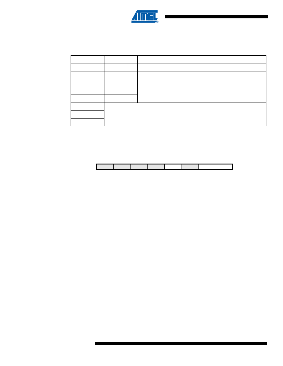
• Bits 2:0 – VLM2:0: Trigger Level of Voltage Level Monitor
These bits set the trigger level for the voltage level monitor, as described in
Table 8-4
below.
For VLM voltage levels, see TBD, TBD and TBD.
8.4.3
RSTFLR – Reset Flag Register
The Reset Flag Register provides information on which reset source caused an MCU Reset.
• Bits 7:4, 2– Res: Reserved Bits
These bits are reserved bits in ATtiny4/5/9/10 and will always read as zero.
• Bit 3 – WDRF: Watchdog Reset Flag
This bit is set if a Watchdog Reset occurs. The bit is reset by a Power-on Reset, or by writing a
logic zero to the flag.
• Bit 1 – EXTRF: External Reset Flag
This bit is set if an External Reset occurs. The bit is reset by a Power-on Reset, or by writing a
logic zero to the flag.
• Bit 0 – PORF: Power-on Reset Flag
This bit is set if a Power-on Reset occurs. The bit is reset only by writing a logic zero to the flag.
To make use of the Reset Flags to identify a reset condition, the user should read and then reset
the MCUSR as early as possible in the program. If the register is cleared before another reset
occurs, the source of the reset can be found by examining the Reset Flags.
Table 8-4.
Setting the Trigger Level of Voltage Level Monitor.
VLM2:0
Label
Description
000
VLM0
Voltage Level Monitor disabled
001
VLM1L
Triggering generates a regular Power-On Reset (POR).
The VLM flag is not set
010
VLM1H
011
VLM2
Triggering sets the VLM Flag (VLMF) and generates a VLM
interrupt, if enabled
100
VLM3
101
Not allowed
110
111
Bit
7
6
5
4
3
2
1
0
0x3B
–
–
–
–
WDRF
–
EXTRF
PORF
RSTFLR
Read/Write
R
R
R
R
R/W
R
R/W
R/W
Initial Value
0
0
0
0
X
0
X
X