2 flash memory, 3 configuration section – Rainbow Electronics ATtiny10 User Manual
Page 109
109
8127B–AVR–08/09
ATtiny4/5/9/10
15.3.2
Flash Memory
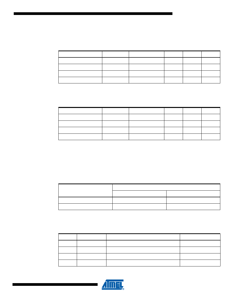
The embedded Flash memory of ATtiny4/5/9/10 has four separate sections, as shown in
Notes:
1. This section is read-only.
Notes:
1. This section is read-only.
15.3.3
Configuration Section
ATtiny4/5/9/10 have one configuration byte, which resides in the configuration section. See
Table 15-6
briefly describes the functionality of all configuration bits and how they are mapped
into the configuration byte.
Table 15-3.
Number of Words and Pages in the Flash (ATtiny9/10)
Section
Size (Bytes)
Page Size (Words)
Pages
WADDR
PADDR
Code (program memory)
1024
8
64
[3:1]
[9:4]
Configuration
8
8
1
[3:1]
–
Signature
16
8
2
[3:1]
[4:4]
Calibration
8
8
1
[3:1]
–
Table 15-4.
Number of Words and Pages in the Flash (ATtiny4/5)
Section
Size (Bytes)
Page Size (Words)
Pages
WADDR
PADDR
Code (program memory)
512
8
32
[3:1]
[9:4]
Configuration
8
8
1
[3:1]
–
Signature
16
8
2
[3:1]
[4:4]
Calibration
8
8
1
[3:1]
–
Table 15-5.
Configuration bytes
Configuration word address
Configuration word data
High byte
Low byte
0x00
Reserved
Configuration Byte 0
0x01 ... 0x07
Reserved
Reserved
Table 15-6.
Configuration Byte 0
Bit
Bit Name
Description
Default Value
7:3
–
Reserved
1 (unprogrammed)
2
CKOUT
System Clock Output
1 (unprogrammed)
1
WDTON
Watchdog Timer always on
1 (unprogrammed)
0
RSTDISBL
External Reset disable
1 (unprogrammed)