3 speed grades, Ltage – Rainbow Electronics ATtiny10 User Manual
Page 117
117
8127B–AVR–08/09
ATtiny4/5/9/10
Notes:
1. All DC Characteristics contained in this data sheet are based on simulation and characterization of other AVR microcon-
trollers manufactured in the same process technology. These values are preliminary values representing design targets, and
will be updated after characterization of actual silicon.
2. “Min” means the lowest value where the pin is guaranteed to be read as high.
3. “Max” means the highest value where the pin is guaranteed to be read as low.
4. Although each I/O port can sink more than the test conditions (10 mA at V
CC
= 5V, 5 mA at V
CC
= 3V) under steady state
conditions (non-transient), the sum of all I
OL
(for all ports) should not exceed 60 mA. If I
OL
exceeds the test conditions, V
OL
may exceed the related specification. Pins are not guaranteed to sink current greater than the listed test condition.
5. Although each I/O port can source more than the test conditions (10 mA at V
CC
= 5V, 5 mA at V
CC
= 3V) under steady state
conditions (non-transient), the sum of all I
OH
(for all ports) should not exceed 60 mA. If I
OH
exceeds the test condition, V
OH
may exceed the related specification. Pins are not guaranteed to source current greater than the listed test condition.
6. The RESET pin must tolerate high voltages when entering and operating in programming modes and, as a consequence,
has a weak drive strength as compared to regular I/O pins. See
, and
16.3
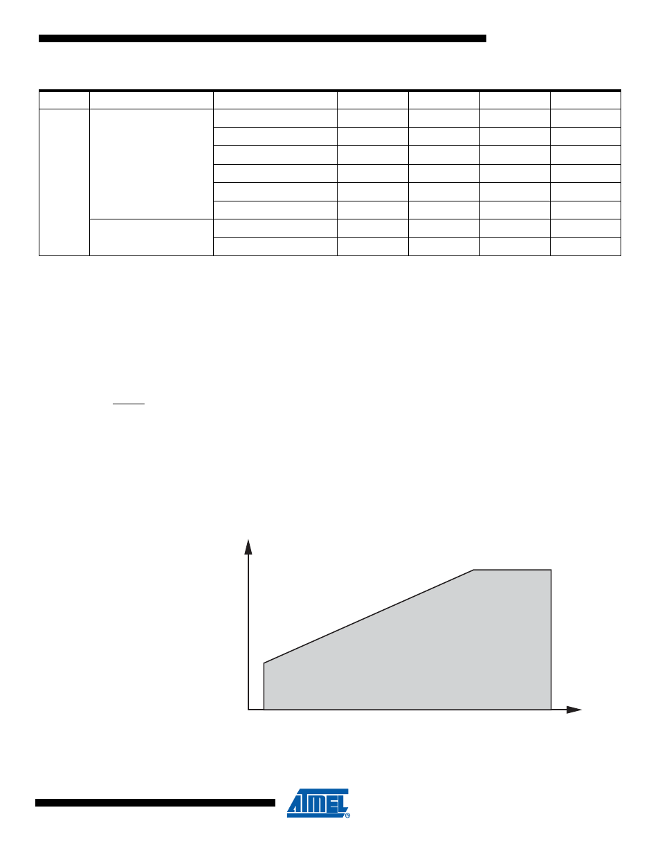
Speed Grades
The maximum operating frequency of the device depends on V
CC
. As shown in
, the
relationship between maximum frequency vs. V
CC
is linear between 1.8V < V
CC
< 4.5V.
Figure 16-1. Maximum Frequency vs. V
CC
I
CC
Power Supply Current
Active 1MHz, V
CC
= 2V
0.33
0.8
mA
Active 4MHz, V
CC
= 3V
1.6
2.5
mA
Active 8MHz, V
CC
= 5V
5
9
mA
Idle 1MHz, V
CC
= 2V
0.11
0.4
mA
Idle 4MHz, V
CC
= 3V
0.4
1.0
mA
Idle 8MHz, V
CC
= 5V
1.5
3.5
mA
Power-down mode
WDT enabled, V
CC
= 3V
4.5
10
µA
WDT disabled, V
CC
= 3V
0.15
2
µA
Table 16-1.
DC Characteristics. T
A
= -40
°
C to +85
°
C
(1)
(Continued)
Symbol
Parameter
Condition
Min.
Typ.
Max.
Units
4 MHz
1.8V
5.5V
4.5V
12 MHz