Rainbow Electronics ATtiny10 User Manual
Page 74
74
8127B–AVR–08/09
ATtiny4/5/9/10
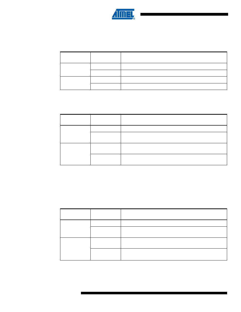
When OC0A or OC0B is connected to the pin, the function of COM0x1:0 bits depends on the
WGM03:0 bits.
Table 11-2
shows the COM0x1:0 bit functionality when the WGM03:0 bits are set
to a Normal or CTC (non-PWM) Mode.
Table 11-3
shows the COM0x1:0 bit functionality when the WGM03:0 bits are set to one of the
Fast PWM Modes.
Note:
1. A special case occurs when OCR0A/OCR0B equals TOP and COM0A1/COM0B1 is set. In
this case the compare match is ignored, but set or clear is done at BOTTOM. See
for more details.
Table 11-4
shows the COM0x1:0 bit functionality when the WGM03:0 bits are set to the phase
correct or the phase and frequency correct, PWM mode.
Note:
1. A special case occurs when OCR0A/OCR0B equals TOP and COM0A1/COM0B1 is set.
“Phase Correct PWM Mode” on page 65
for more details.
Table 11-2.
Compare Output in Non-PWM Modes
COM0A1/
COM0B1
COM0A0
COM0B0
Description
0
0
Normal port operation: OC0A/OC0B disconnected
1
Toggle OC0A/OC0B on compare match
1
0
Clear (set low) OC0A/OC0B on compare match
1
Set (high) OC0A/OC0B on compare match
Table 11-3.
Compare Output in Fast PWM Modes
COM0A1/
COM0B1
COM0A0/
COM0B0
Description
0
0
Normal port operation: OC0A/OC0B disconnected
1
WGM03 = 0: Normal port operation, OC0A/OC0B disconnected
WGM03 = 1: Toggle OC0A on compare match, OC0B reserved
1
0
Clear OC0A/OC0B on compare match
Set OC0A/OC0B at BOTTOM (non-inverting mode)
1
Set OC0A/OC0B on compare match
Clear OC0A/OC0B at BOTTOM (inverting mode)
Table 11-4.
Compare Output in Phase Correct and Phase & Frequency Correct PWM Modes
COM0A1/
COM0B1
COM0A0/
COM0B0
Description
0
0
Normal port operation: OC0A/OC0B disconnected.
1
WGM03 = 0: Normal port operation, OC0A/OC0B disconnected
WGM03 = 1: Toggle OC0A on compare match, OC0B reserved
1
0
Counting up: Clear OC0A/OC0B on compare match
Counting down: Set OC0A/OC0B on compare match
1
Counting up: Set OC0A/OC0B on compare match
Counting down: Clear OC0A/OC0B on compare match