Clock system, 1 clock subsystems, 1 cpu clock – clkcpu – Rainbow Electronics ATtiny10 User Manual
Page 17: 2 i/o clock – clki/o, 3 nvm clock - clknvm
17
8127B–AVR–08/09
ATtiny4/5/9/10
6.
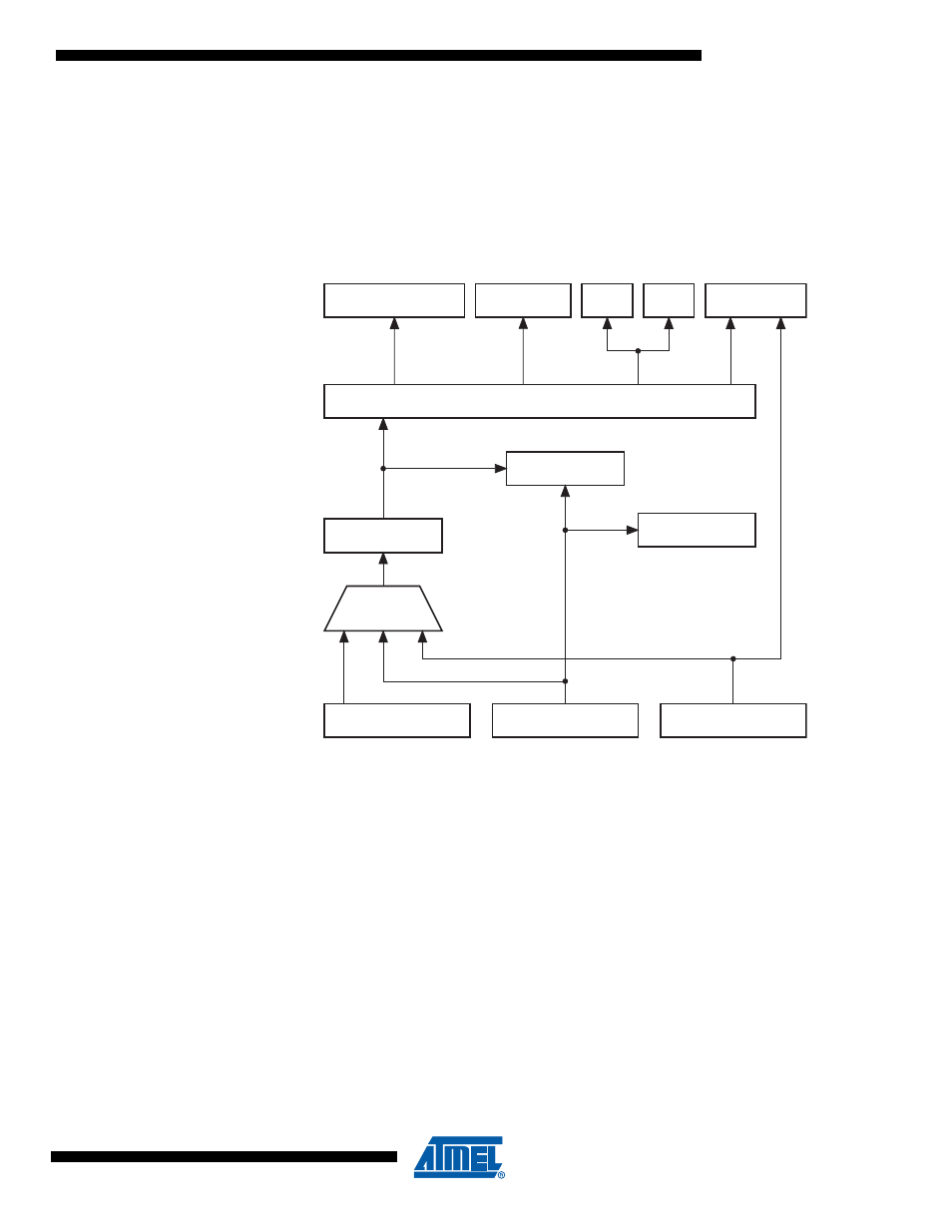
Clock System
Figure 6-1
presents the principal clock systems and their distribution in ATtiny4/5/9/10. All of the
clocks need not be active at a given time. In order to reduce power consumption, the clocks to
modules not being used can be halted by using different sleep modes and power reduction reg-
ister bits, as described in
“Power Management and Sleep Modes” on page 23
. The clock
systems is detailed below.
Figure 6-1.
Clock Distribution
6.1
Clock Subsystems
The clock subsystems are detailed in the sections below.
6.1.1
CPU Clock – clk
CPU
The CPU clock is routed to parts of the system concerned with operation of the AVR Core.
Examples of such modules are the General Purpose Register File, the System Registers and
the SRAM data memory. Halting the CPU clock inhibits the core from performing general opera-
tions and calculations.
6.1.2
I/O Clock – clk
I/O
The I/O clock is used by the majority of the I/O modules, like Timer/Counter. The I/O clock is
also used by the External Interrupt module, but note that some external interrupts are detected
by asynchronous logic, allowing such interrupts to be detected even if the I/O clock is halted.
6.1.3
NVM clock - clk
NVM
The NVM clock controls operation of the Non-Volatile Memory Controller. The NVM clock is usu-
ally active simultaneously with the CPU clock.
CLOCK CONTROL UNIT
GENERAL
I/O MODULES
ANALOG-TO-DIGITAL
CONVERTER
CPU
CORE
WATCHDOG
TIMER
RESET
LOGIC
CLOCK
PRESCALER
RAM
CLOCK
SWITCH
NVM
CALIBRATED
OSCILLATOR
clk
ADC
SOURCE CLOCK
clk
I/O
clk
CPU
clk
NVM
WATCHDOG
CLOCK
WATCHDOG
OSCILLATOR
EXTERNAL
CLOCK