5 system and reset characteristics, 1 power-on reset, 2 vcc level monitor – Rainbow Electronics ATtiny10 User Manual
Page 119: Defined in section
119
8127B–AVR–08/09
ATtiny4/5/9/10
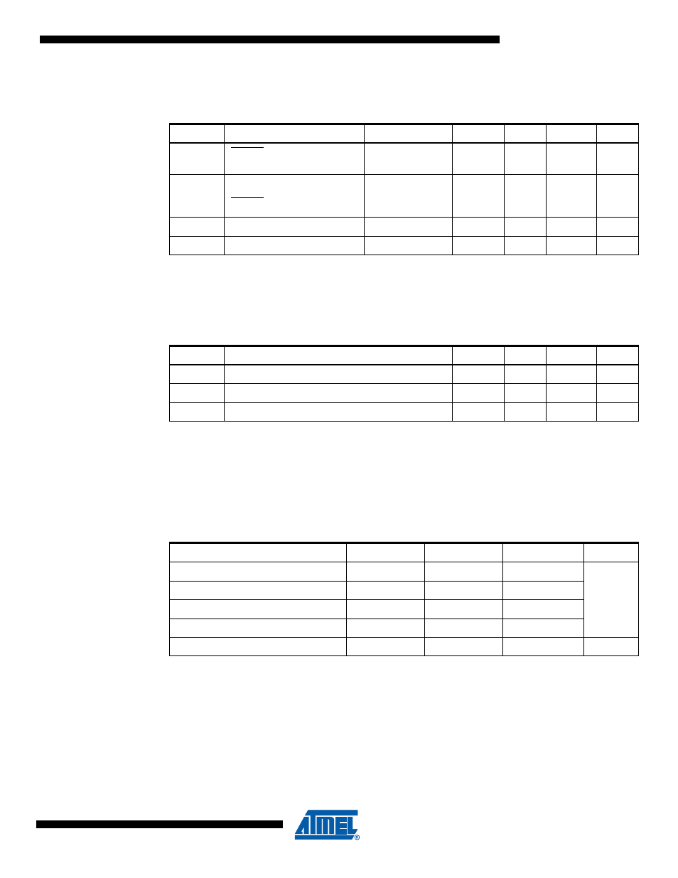
16.5
System and Reset Characteristics
Note:
1. Values are guidelines, only
16.5.1
Power-On Reset
Note:
1. Values are guidelines, only
2. Threshold where device is released from reset when voltage is rising
3. The Power-on Reset will not work unless the supply voltage has been below V
POT
(falling)
16.5.2
V
CC
Level Monitor
Note:
1. Typical values at room temperature
Table 16-4.
Reset, VLM, and Internal Voltage Characteristics
Symbol
Parameter
Condition
Typ
Max
Units
V
RST
RESET Pin Threshold
Voltage
0.2 V
CC
0.9V
CC
V
t
RST
Minimum pulse width on
RESET Pin
V
CC
= 1.8V
V
CC
= 3V
V
CC
= 5V
2000
700
400
ns
t
TOUT
Time-out after reset
64
128
ms
V
HYST
VLM Hysteresis
50
mV
Table 16-5.
Characteristics of Enhanced Power-On Reset.
T
A
= -40 - 85
°
C
Symbol
Parameter
Min
(1)
Typ
(1)
Max
(1)
Units
V
POR
Release threshold of power-on reset
(2)
1.1
1.4
1.6
V
V
POA
Activation threshold of power-on reset
(3)
0.6
1.3
1.6
V
SR
ON
Power-On Slope Rate
0.01
V/ms
Table 16-6.
Voltage Level Monitor Thresholds
Parameter
Min
Typ
Max
Units
Trigger level VLM1L
1.1
1.4
1.6
V
Trigger level VLM1H
1.4
1.6
1.8
Trigger level VLM2
2.0
2.5
2.7
Trigger level VLM3
3.2
3.7
4.5
Settling time
TBD
TBD
TBD
µs