Texas Instruments TMS320C3x User Manual
Page 99
Reset/Interrupt/Trap Vector Map
4-17
Memory and the Instruction Cache
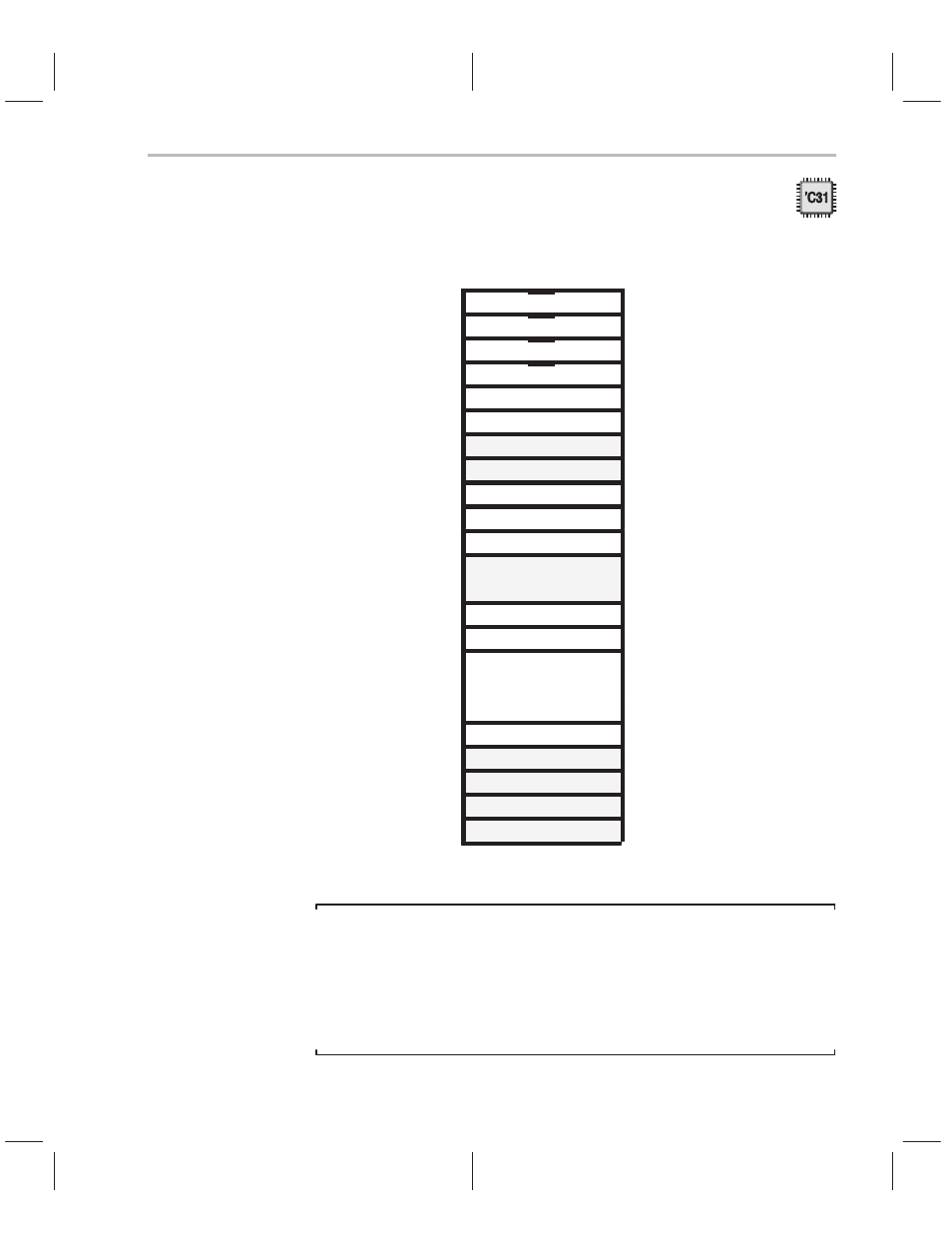
Figure 4–9. Interrupt and Trap Branch Instructions for the TMS320C31
Microcomputer Mode
809FC1h
INT0
809FC2h
INT1
809FC3h
INT2
809FC4h
INT3
809FC5h
XINT0
809FC6h
RINT0
809FC7h
XINT1 (reserved)
809FC8h
RINT1 (reserved)
809FC9h
TINT0
809FCAh
TINT1
809FCBh
DINT
809FCCh
809FDFh
Reserved
809FE0h
TRAP 0
809FE1h
TRAP 1
•
•
•
809FFBh
TRAP 27
809FFCh
TRAP 28 (reserved)
809FFDh
TRAP 29 (reserved)
809FFEh
TRAP 30 (reserved)
809FFFh
TRAP 31 (reserved)
Note:
Traps 28–31
Traps 28–31 are reserved; do not use them.
Unlike the ’C31’s microprocessor mode, the ’C31 microcomputer/boot loader
mode uses a dual-vectoring scheme to service interrupts and trap requests. In
this dual vectoring scheme, a branch instruction rather than a vector address
is used.
- Digital Signal Processor SM320F2812-HT (153 pages)
- MSP430x1xx (440 pages)
- Laser And Motor Drives DRV8811EVM (13 pages)
- TMS320 DSP (88 pages)
- MSP430x11x1 (45 pages)
- TVP5154EVM (55 pages)
- TMS320DM646X DMSOC (64 pages)
- CC2511 (24 pages)
- SN65HVS880 (4 pages)
- TPS650231EVM (14 pages)
- TMS320TCI648x (256 pages)
- TSC2007EVM-PDK (16 pages)
- UCC38500EVM (16 pages)
- TMS320C6000 (62 pages)
- SCAU020 (21 pages)
- TPS40051 (17 pages)
- TNETE2201 (14 pages)
- TMS320C64x DSP (306 pages)
- UCC2891 (21 pages)
- MSP430 (138 pages)
- TMS320C6712D (102 pages)
- MSP430x4xx (512 pages)
- TMS320C6454 (225 pages)
- SPRU938B (48 pages)
- TUSB3210 (22 pages)
- TMS320C6457 (43 pages)
- CC2530ZNP (3 pages)
- TMS320C6455 (50 pages)
- TSB12LV26 (91 pages)
- TMS320C6472 (2 pages)
- VLYNQ Port (49 pages)
- TMS380C26 (92 pages)
- MSP-FET430 (95 pages)
- TMS320TCI6486 (160 pages)
- TPS2330 (22 pages)
- DM648 DSP (47 pages)
- TMS320DM36X (134 pages)
- MSC1211 (35 pages)
- SPRAA56 (29 pages)
- DAC7741EVM (28 pages)
- CDCM7005 (34 pages)
- TMS370 (99 pages)
- Adpater (37 pages)
- TMS320C6452 DSP (46 pages)