Texas Instruments TMS320C3x User Manual
Page 241
3
PC
Fetch held for
new PC value
Pipeline Conflicts
8-5
Pipeline Operation
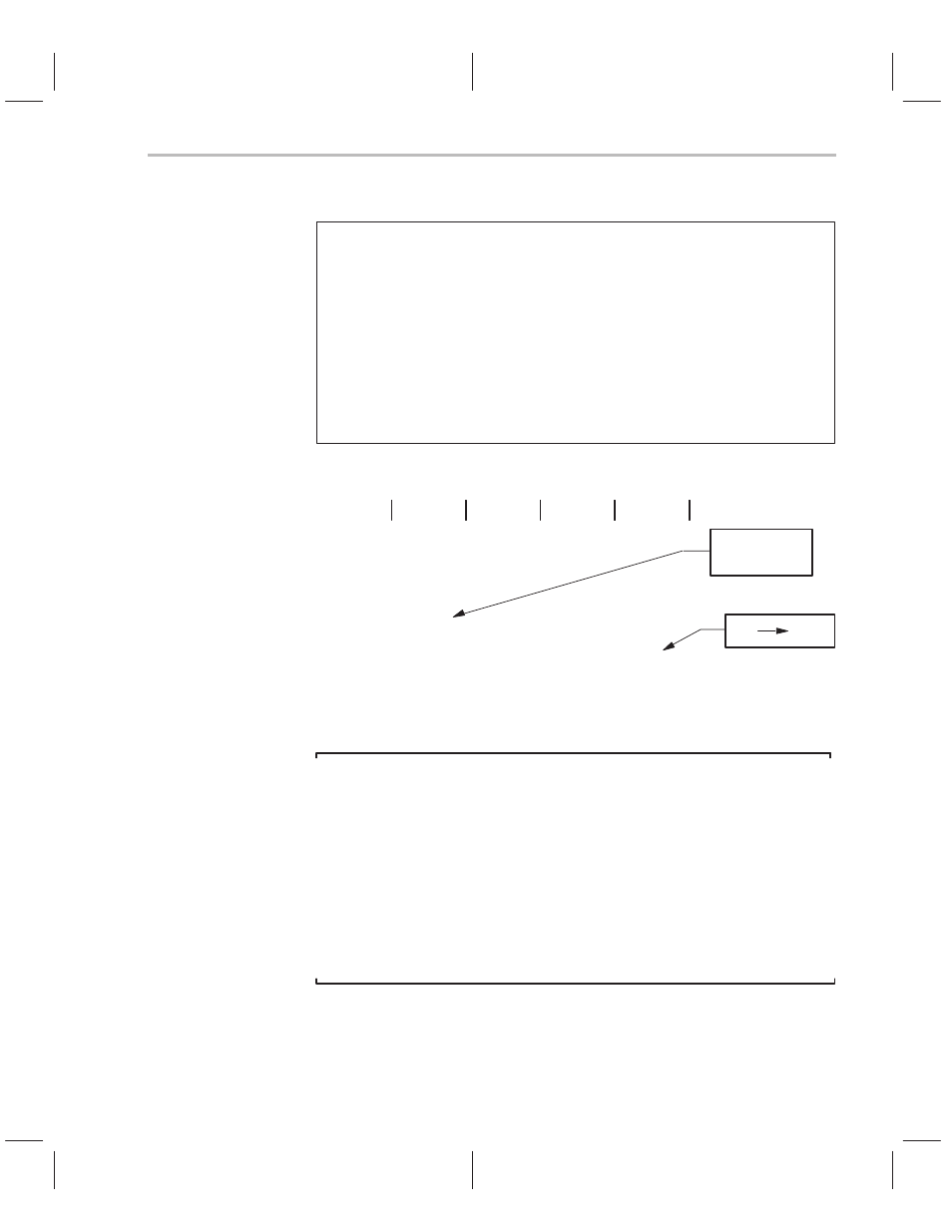
Example 8–1. Standard Branch
BR
THREE
; Unconditional branch
MPYF
; Not executed
ADD
; Not executed
SUBF
; Not executed
AND
; Not executed
.
.
.
THREE
OR
; Fetched after BR is taken
STI
.
.
.
Pipeline Operation
PC
Fetch
Decode
Read
Execute
n
BR
—
—
—
n+1
MPYF
BR
—
—
n+1
(nop)
(nop)
BR
—
n+1
(nop)
(nop)
(nop)
BR
3
OR
(nop)
(nop)
(nop)
STI
OR
(nop)
(nop)
Note:
Both RPTS and RPTB flush the pipeline, allowing the RS, RE, and RC registers
to be loaded at the proper time. If these registers are loaded without the use of
RPTS or RPTB, no flushing of the pipeline occurs. Thus, RS, RE, and RC can
be used as general-purpose 32-bit registers without pipeline conflicts. When
RPTB is nested because of nested interrupts, it may be necessary to load and
store these registers directly while using the repeat modes. Since up to four
instructions can be fetched before entering the repeat mode, you should follow
loads by a branch to flush the pipeline. If the RC is changing when an instruc-
tion is loading it, the direct load takes priority over the modification made by
the repeat mode logic.
Delayed branches are implemented to ensure the fetching of the next three
instructions. The delayed branches include BRD, B
condD, and DBcondD.
Example 8–2 shows the code and pipeline operation for a delayed branch.