Texas Instruments TMS320C3x User Manual
Page 316
Configuration
10-13
TMS320C32 Enhanced External Memory Interface
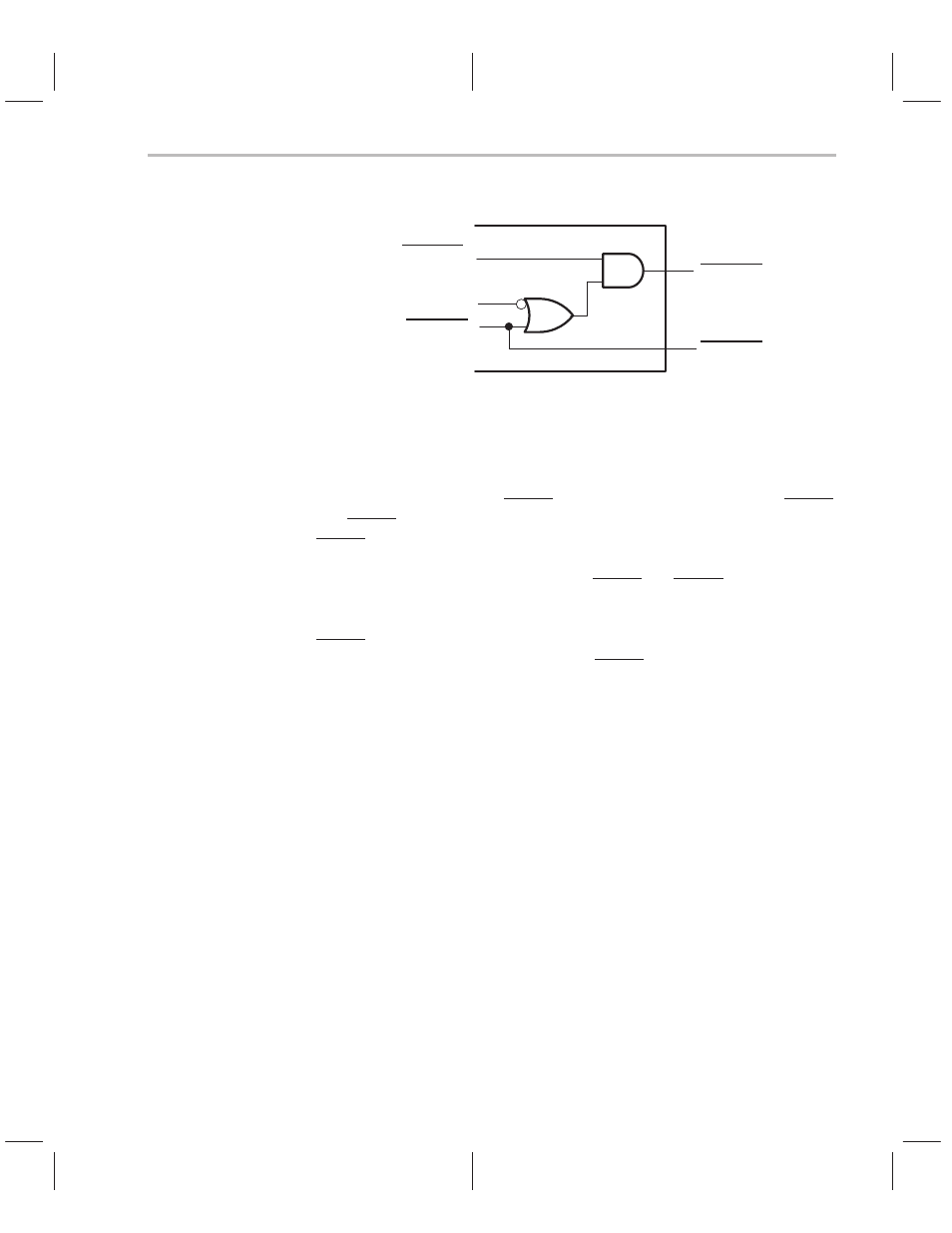
Figure 10–7. STRB Configuration
STRB0_Bx
STRB1_Bx
STRB0_Bx
STRB config
STRB1_Bx
10.3.2 Using Physical Memory Width and Data-Type Size Fields
Consider a ’C32 connected to two banks of external memory. In this configura-
tion, one bank is mapped to STRB0 while the other bank is mapped to STRB1.
The STRB0 bank of memory is 32 bits wide and stores 32-bit data types. The
STRB1 bank of memory is 16 bits wide and stores 16-bit data types. You can
transfer these configurations to the ’C32 by setting the physical memory width
and data-type size fields of the respective STRB0 and STRB1 control registers.
You also must clear the STRB config bit field to 0 since the banks are separate
memories. Note that ‘C32 address pins A
23
A
22
A
21
...A
1
A
0
are connected to the
STRB0 memory bank address pins A
23
A
22
A
21
...A
1
A
0
. But ’C32 address pins
A
22
A
21
...A
1
A
0
A
–
1
are connected to the STRB1 memory-bank address pins
A
23
A
22
A
21
...A
1
A
0
.
Executing the following code on this device results in the data-access
sequence shown in Table 10–2.
ББ
ББ
ББ
ББ
ББ
ББ
ББ
ББ
ББ
1)
2)
3)
4)
5)
6)
7)
8)
9)
ББББ
Б
ББ
Б
Б
ББ
Б
Б
ББ
Б
Б
ББ
Б
Б
ББ
Б
Б
ББ
Б
Б
ББ
Б
ББББ
LDI
LDI
ADDI
ADDI
ADDI
LDI
LSH
LDI
ADDI
БББББ
Б
БББ
Б
Б
БББ
Б
Б
БББ
Б
Б
БББ
Б
Б
БББ
Б
Б
БББ
Б
Б
БББ
Б
БББББ
4000h, AR1
*AR1++, R2
*AR1++, R2
*AR1++, R2
*AR1++, R2
900h, AR2
12, AR2
*AR2++, R3
*AR2, R3
БББББББББББББББ
Б
БББББББББББББ
Б
Б
БББББББББББББ
Б
Б
БББББББББББББ
Б
Б
БББББББББББББ
Б
Б
БББББББББББББ
Б
Б
БББББББББББББ
Б
Б
БББББББББББББ
Б
БББББББББББББББ
; AR1 = 4000h
; R2 = *4000h and AR1 = AR1 + 1
; R2 = R2 + *4001h and AR1 = AR1 + 1
; R2 = R2 + *4002h and AR1 = AR1 + 1
; R2 = R2 + *4003h and AR1 = AR1 + 1
; AR2 = 900h
; AR2 = 900000h
; R3 = *900000h and AR2 = AR2 + 1
; R3 = R3 + 900001h