I/o flag (iof) register, 10 i/o flag (iof) register, Figure 3–12. i/o flag (iof) register – Texas Instruments TMS320C3x User Manual
Page 79: Table 3–5. iof bits and functions
CPU Multiport Register File
3-16
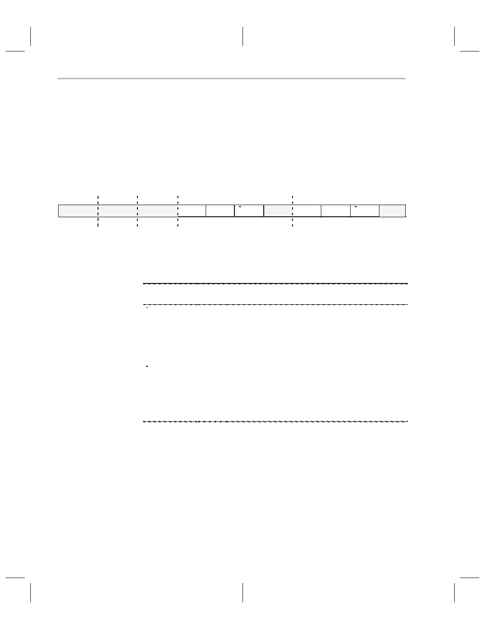
3.1.10 I/O Flag (IOF) Register
The I/O flag (IOF) register is shown in Figure 3–12 and controls the function
of the dedicated external pins, XF0 and XF1. These pins can be configured for
input or output. The pins can also be read from and written to. At reset, 0 is
written to this register. Table 3–5 describes the I/O flags register bits, their
names, and their functions.
Figure 3–12. I/O Flag (IOF) Register
R
R/W
R/W
R
R/W
R/W
INXF1
7
OUTXF1
6
I/OXF1
5
INXF0
3
OUTXF0
2
I/OXF0
1
xx
0
11–8
15–12
31–16
4
xx
xx
xx
xx
Notes:
1) xx = reserved bit, read as 0
2) R = read, W = write
Table 3–5. IOF Bits and Functions
Bit Name
Reset
Value
Function
I/OXF0
0
If 0, XF0 is configured a general-purpose input pin.
If 1, XF0 is configured a general-purpose output pin.
OUTXF0
0
Data output on XF0.
INXF0
0
Data input on XF0. A write has no effect.
I/OXF1
0
If 0, XF1 is configured a general-purpose input pin.
If 1, XF1 is configured a general-purpose output pin.
OUTXF1
0
Data output on XF1.
INXF1
0
Data input on XF1. A write has no effect.