Chapter4 basic operations, Internal states, Basic operations – IDEC FS1A Controller User Manual
Page 39
BASIC OPERATIONS
4-1
Chapter 4
Chapter4 BASIC
OPERATIONS
This chapter describes the basic operations of SafetyOne. Make proper use of the
SafetyOne by thoroughly familiarizing yourself with basic operations and functions.
Internal states
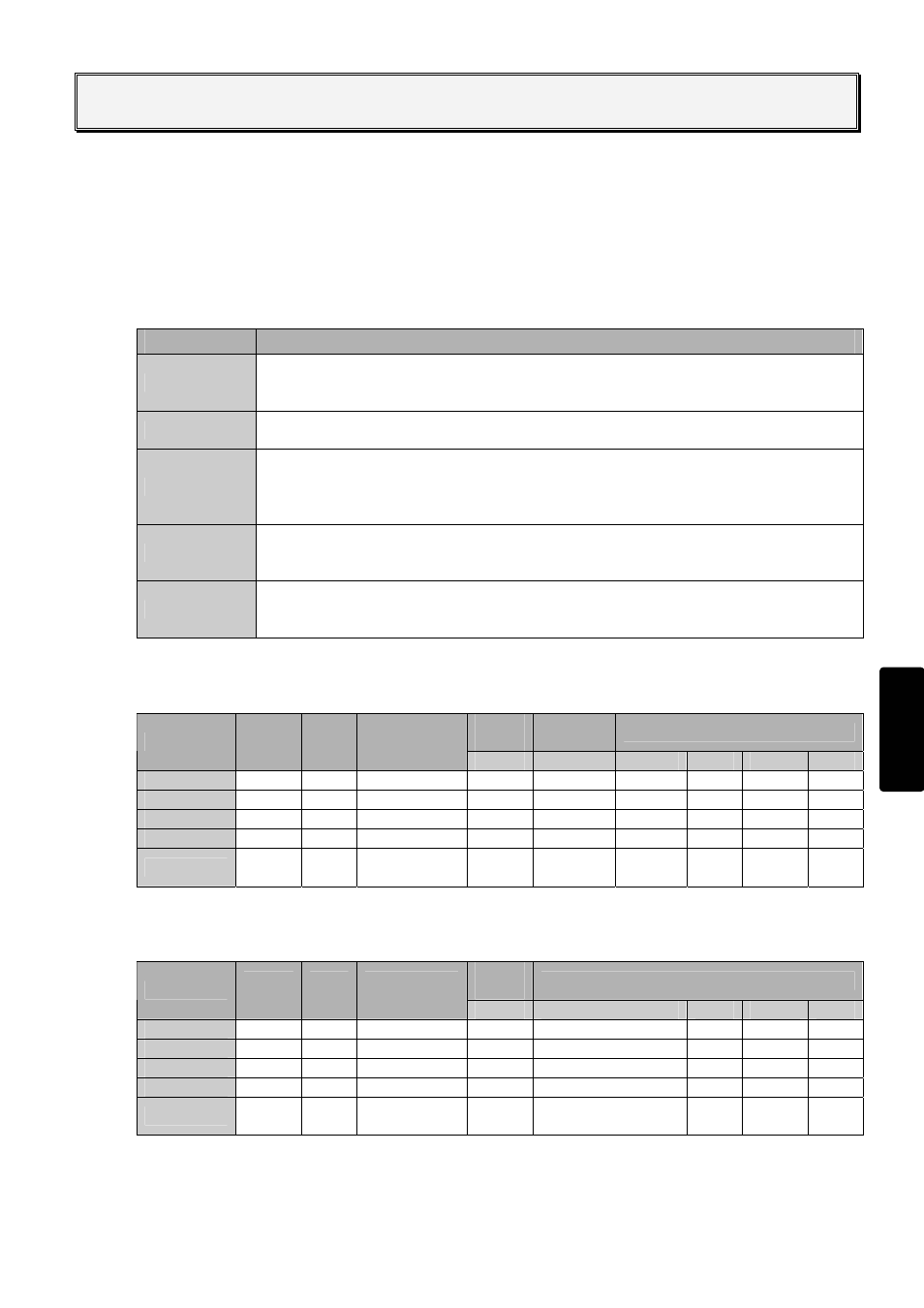
The SafetyOne operates in five internal states, as shown in Table 4.1.
The LED display and output status for each state are shown in Table 4.2.1and 4.2.2.
Table 4.1 Internal states
State
Description
Initial
Initial processing is performed immediately after power is supplied to the SafetyOne.
The internal circuits are checked and the LEDs show operation confirmation (blinking)
for 6 seconds (approx)..
Run
The SafetyOne is under normal operation. Logic processing continues without failures
or wiring errors. (Refer to "Chapter 5 LOGIC" for details.)
Configuration
A logic or OFF-delay timer value is being configured.
Configuration enables the logic and OFF-delay timer value. When completed, the
SafetyOne changes to the Run state. (Refer to "Logic configuration" and "Timer
configuration" in this chapter for details.)
Protection
An input monitor error has occurred with dual channel input, EDM input, or muting
input. When the problem is removed, the SafetyOne changes to Run state. (Refer to
"Canceling the Protection state" in this chapter for details.)
Stop
A failure or error has occurred with an external device or internal circuit. When the
problem is removed and the power is turned on, Stop state is cleared. (Refer to
"Canceling the Stop state" in this chapter for details.)
Table 4.2.1 LED display and output status for each state
(When safety outputs are dual channel outputs)
Safety
output
Solenoid/
lamp output
Monitor output
State
Logic
LED
Error
LED
Timer
LED
Y0…Y3
Y17,Y20
Y4…Y13
Y14
Y15
Y16
Initial (1)
(1)
(1)
□
OFF
□
OFF
□
OFF
■
ON
■
ON
□
OFF
Run
Logic #
Blank
Selected Value
(2)
(2)
(2)
□
OFF
□
OFF
■
ON
Configuration (3)
“C” (3)
□
OFF
□
OFF
□
OFF
□
OFF
■
ON
□
OFF
Protection
Logic #
“1”
Selected Value
□
OFF
(6)
□
OFF
(4) □
OFF
■
ON
□
OFF
Stop Blank
(5)
Blank □
OFF
□
OFF
(4) ■
ON
■
ON
or
□
OFF
□
OFF
Table 4.2.2 LED display and output status for each state
(When safety outputs are single channel outputs)
Safety
output
Monitor output
State
Logic
LED
Error
LED
Timer
LED
Y0…Y3
Y4…Y13, Y17, Y20
Y14
Y15
Y16
Initial (1)
(1)
(1)
□
OFF
□
OFF
■
ON
■
ON
□
OFF
Run
Logic #
Blank
Selected Value
(2)
(2)
□
OFF
□
OFF
■
ON
Configuration (3)
“C” (3)
□
OFF
□
OFF
□
OFF
■
ON
□
OFF
Protection
Logic #
“1”
Selected Value
□
OFF
(6) (4)
□
OFF
■
ON
□
OFF
Stop Blank
(5)
Blank □
OFF
(4)
■
ON
■
ON
or
□
OFF
□
OFF