Timing chart (logic 103), Logic, Example: teach mode – IDEC FS1A Controller User Manual
Page 190
LOGIC
5-142
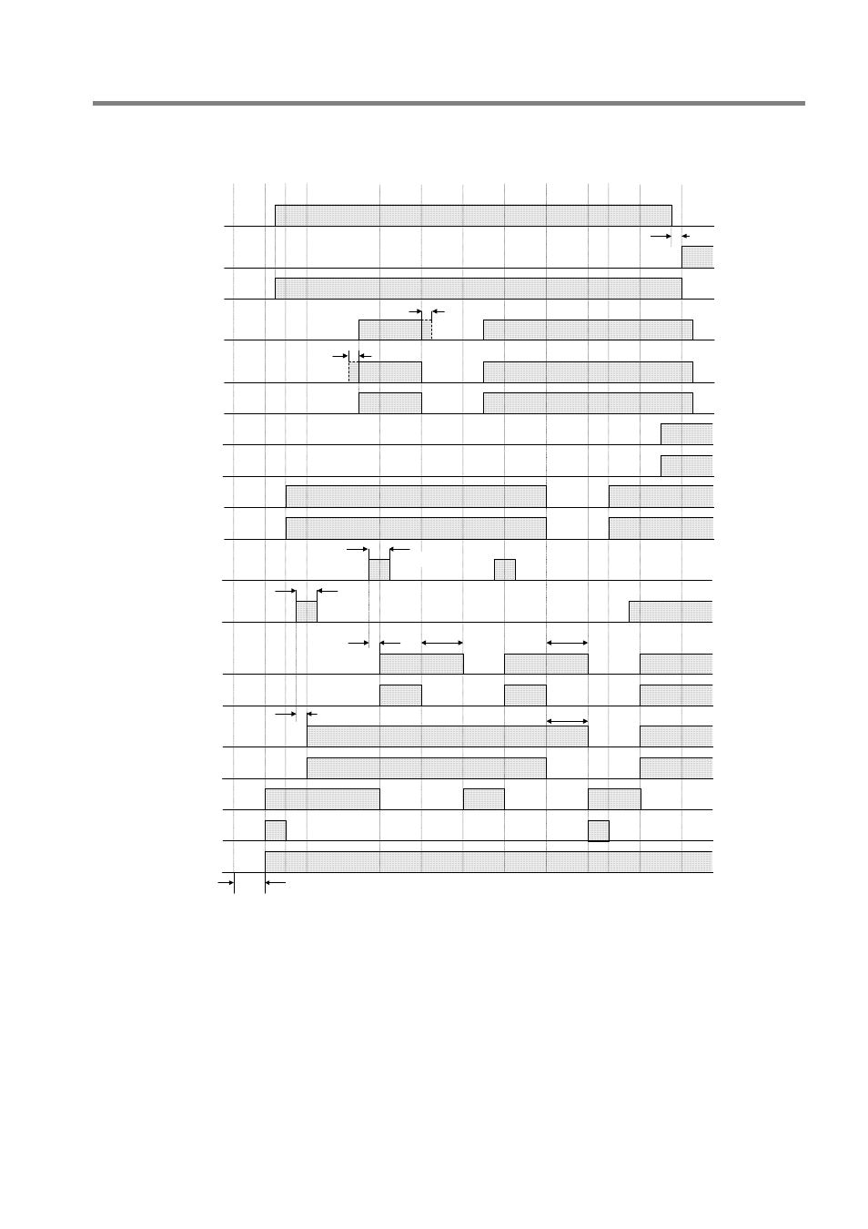
Timing chart (Logic 103)
Example: Teach mode
Max. 0.1s
Monitor output for
safety input 4: Y7
Safety input 4: X6,
X7
Safety output 2:
Y2, Y3
Safety input 1: X0
(Mode select input:
Teach mode)
Safety input 2: X2
Monitor output for
safety input 2: Y5
Monitor output for
safety input 1: Y4
Monitor output for
safety input 6: Y11
Start input 1: X16
(Manual)
Safety input 1: X1
(Mode select input:
Auto mode)
Max. 6s
Initialization
Monitor output for
Safety output 1: Y12
Solenoid output 2:
Y20
State monitor output 3:
Y16
Safety input 6: X12,
X13
Start input 2: X17
(Control)
Safety input 2: X3
note 2)
note 2)
Safety output 1:
Y0, Y1
Min. 0.1s
Monitor output for
Safety output 2: Y13
Solenoid output 1:
Y17
Max. 0.1s
Switch
to auto
mode
Max. 3s
note 1)
Min. 0.1s
Power
ON
Safety
output
2
ON
Safety
output
1
ON
OFF delay time
OFF delay time
OFF delay time
Safety
output
1
ON
Safety
output
1, 2
ON
(Both safety input 3 and 5 are ON in this chart.)
Note 1) When “Safety input 1(mode select input)” is switched to another mode within 3s, “Safety output 1” is kept
ON. ”Safety output 2" is unrelated to mode select input.
Note 2) Input monitor error detection time is infinity.
About safety inputs that are not described in this chart, input monitor error detection time is as follows.
The time of dual channel dependent input (X4, X5, X12 and X13) is infinity.
The time of dual channel direct opening input (X6, X7) is 0.5s.
The time of dual channel safety input (X10, X11) is 0.1s.
Refer to the following “Logic functions” for more details.