Dual channel no/nc input, Connects to, Description of operation – IDEC FS1A Controller User Manual
Page 363
LOGIC
5-315
Chapter 5
Dual channel NO/NC input
This function is for connecting safety devices with dual channel NO/NC mechanisms, such as
non-contact interlock switches. As shown in Fig. 5-5, this function is comprised of a dual channel
input receiving circuit (X
n
, X
n+1
), a drive circuit (T
n
, T
n+1
), and a functional output (I
n
). Because
safety devices comprised of NO and NC contacts are connected, during normal operation, 1 of the
dual channel inputs is ON while the other is OFF.
Fig. 5-5 Circuit for dual channel NO/NC input function
Connects to
Safety devices with NO/NC contacts, such as non-contact interlock switches.
Note. This cannot be connected to a safety light curtain or any other safety solid state output.
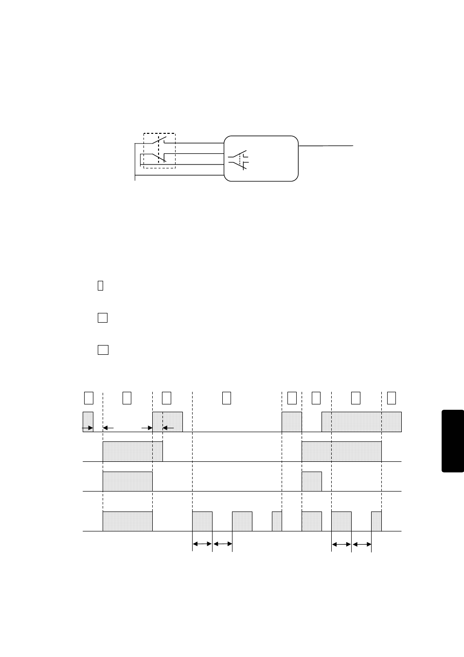
Description of operation
The operation timing is described in Fig. 5-6.
I When a safety check signal from 1 of the 2 drive circuits (T
n+1
) is supplied to the
corresponding receiving circuit (X
n+1
) and the other receiving circuit (X
n
) is OFF, the output is
turned ON. (Ex. Guard is closed.)
II When a safety check signal from 1 of the 2 drive circuits (T
n
) is supplied to the corresponding
receiving circuit (X
n
), and the other receiving circuit (X
n+1
) is OFF, the output is turned OFF.
(Ex. Guard is opened.)
III If safety check signals are not supplied correctly to the receiving circuits, due to an error in
the safety device or input circuit, the output is turned OFF immediately. Status of any
detected error is displayed on the error LED, input LEDs and monitoring output. (Ex. Fault in
the non-contact Interlock switch)
X
n
X
n+1
I
n
ON
OFF
Independent conditon
change in one input
Y
m
(Monitor output)
0.5s
0.5s
Ⅰ
Ⅱ
Ⅲ
Ⅱ
Ⅰ
Ⅱ
ON
OFF
ON
OFF
ON
OFF
Ⅱ
Cance-
llation
SafetyOne changes to
Protection State after an input
monitor error is detected.
1Hz pulse signal is output from
corresponded monitor output.
Input monitor
error detection
time:Max.0.5s
0.5s
0.5s
Cance-
llation
SafetyOne
changes to
Protection State
after an input
monitor error is
detected.
Ⅲ
Independent conditon
change in one input
Fig. 5-6 Operation timing of a dual channel NO/NC input function
X
n
T
n
X
n+1
T
n+1
I
n
Safety device
Dual Channel
NO/NC