Mode select input ii, Connects to, Description of operation – IDEC FS1A Controller User Manual
Page 369
LOGIC
5-321
Chapter 5
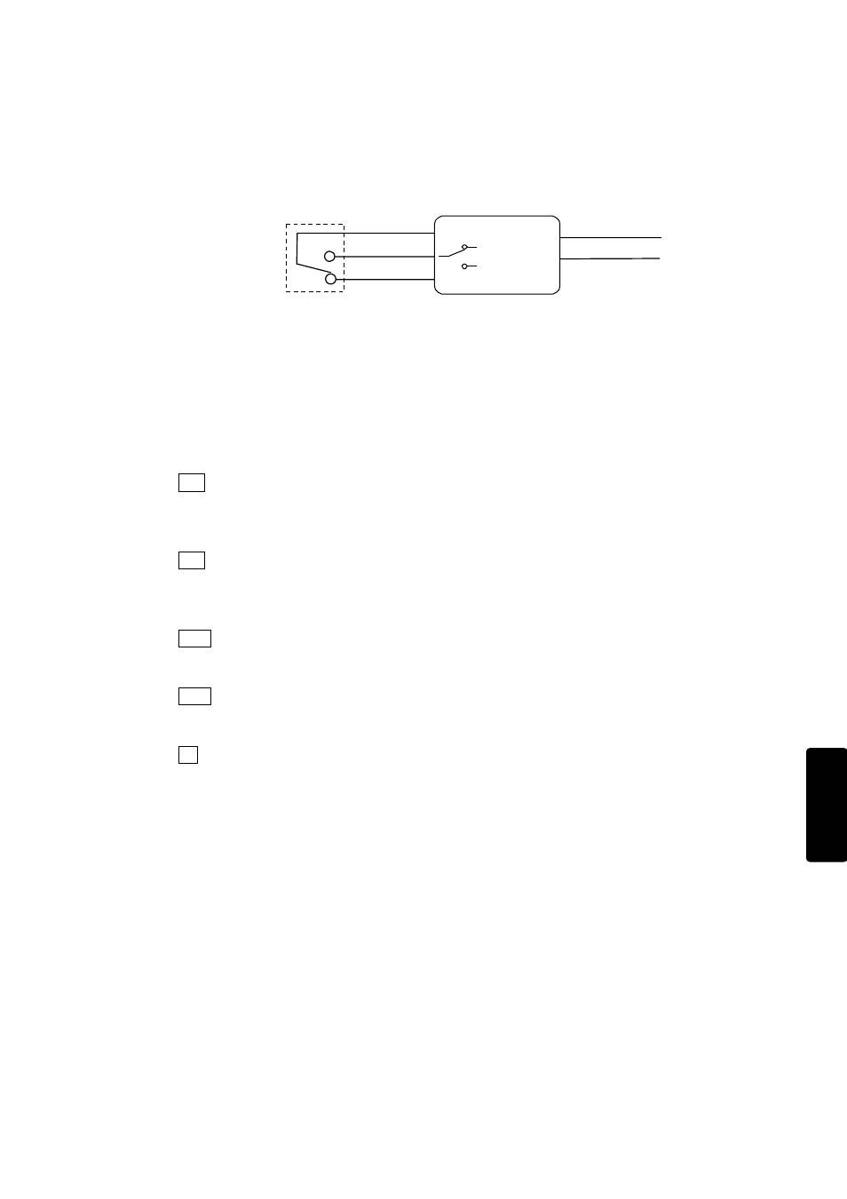
Mode select input II
This function is for connecting devices with a mode select function, such as a selector switch. In
case of switching the input is performed within 3 s, the function output is kept at previous state.
As shown in Fig. 5-11, this function is comprised of 2 input receiving circuits (X
n
, X
n+1
), 1 drive
circuit (T
n
), and functional output (TEACH, AUTO).
Fig. 5-11 Circuit for mode select input II function
Connects to
Mode selecting device such as a selector switch or a rotary switch
Note. This cannot be connected to a safety light curtain or any other safety solid state output.
Description of operation
The operation timing is described in Fig. 5-12.
I-1 When a safety check signal from the drive circuit (T
n
) is supplied to 1 of the receiving circuits
(X
n+1
), and the other receiving circuit (X
n
) is OFF, the output “AUTO” is turned ON. The
output “AUTO” is kept ON state within input switching time (3s: the time from receiving
circuit (X
n+1
) is turned OFF to receiving circuit (X
n
) is turned ON).
I-2 When a safety check signal from the drive circuit (T
n
) is supplied to 1 of the receiving circuits
(X
n
), and the other receive circuit (X
n+1
) is OFF, the output “TEACH” is turned ON. The
output “TEACH” is kept ON state within input switching time (3s: the time from receiving
circuit (X
n
) is turned OFF to receiving circuit (X
n+1
) is turned ON).
II-1 When both receiving circuits are OFF over the input switching time (3s), both of outputs
“TEACH” and “AUTO” are turned OFF. (Ex. The selector switch is in the intermediate
position.)
II-2 When both receiving circuits are ON, both of outputs “TEACH” and “AUTO” are turned OFF.
And if the input monitoring error detection time (0.5s) is exceeded during the time both
receiving circuits are ON, an input monitoring error is detected.
III If safety check signals are not supplied correctly to the receiving circuits due to an error in
the selected mode device or input circuit, the output is turned OFF immediately. Status of
the error is displayed by the error LED, input LEDs, and the monitoring output. (Ex. Fault
in selector switch or wiring error)
X
n
T
n
X
n+1
Mode selector device
TEACH
AUTO
Mode
Select
Ⅱ