IDEC FS1A Controller User Manual
Page 208
LOGIC
5-160
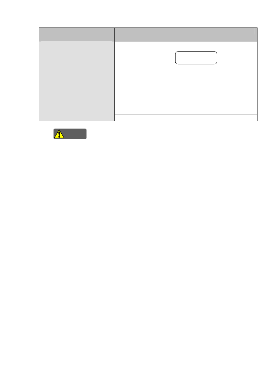
Intended inputs
(Terminal names)
Function
Function name
Dual channel safety input
Symbol
Dual Channel Safety
Description of operation
This function diagnoses the status of
connected safety devices. This function
diagnoses the time interval of status
transition between each input of
duplicated inputs (0.1s). The function
does not use drive terminals (T6, T7,
T10 and T11).
Safety input 4
(X6,X7)
Safety input 5
(X10, X11)
Detail information
Logic functions (5-317)
Warning
For connected control devices, refer to “SAFETY PRECAUTIONS”.
Safety check signals (pulses signals) are sent from the drive terminals (T0, T2 to T5, T12, T13) to
diagnose connected safety devices and input circuits. Safety check signals can not be used as a
power supply for connected devices.
In case of using only one of safety input 4 or safety input 5, open the unused safety inputs. If the
unused safety input is connected to a 24 VDC power supply (V+), SafetyOne does not turns OFF by
the OFF operation of used safety input.
Note. Solid state outputs, such as safety light curtains, can not be connected to safety input 1 through
Safety input 3, and safety input 6.
Note. Use safety input 1 through safety input 3, and safety input 6, as specified combinations, such as
receive terminal (Xn) and drive terminal (Tn). If the combinations are incorrect, SafetyOne does
not work correctly.
Note. When SafetyOne is in Run state or Protection state, input states are monitored in all safety
inputs. For example, if input monitor error is detected in safety input 2 although AUTO mode is
selected, SafetyOne detects error and transits to Protection state.
Note. If there are unused safety inputs in safety input 2, safety input 3, or safety input 6, connect the
unused receive terminals (Xn) to the corresponding drive terminals (Tn). If they are not
connected, the SafetyOne does not turn ON the safety outputs.