Timing chart (logic 102) – IDEC FS1A Controller User Manual
Page 126
LOGIC
5-78
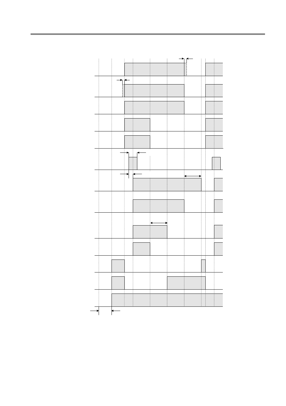
Timing chart (Logic 102)
Example: Manual start input (X16) is used.
OFF delay time
OFF delay time
Safety input 1: X0
Start input 1: X16
(Manual)
Safety output 1: Y0,
Y1
Monitor output for
safety input 1: Y4
Monitor output for
Safety output 1: Y12
State monitor output 3:
Y16
Solenoid output 2:
Y20
Safety input 1: X1
Min. 0.1s
Max. 6s
Initialization
note 1)
Max. 0.1s
note 1)
Safety input 4: X6,
X7
Monitor output for
safety input 4: Y7
Safety output 2:
Y2, Y3
Monitor output for
Safety output 2: Y13
Solenoid output 1:
Y17
Power
ON
Safety
output
ON
Safety
output
ON
(Safety input 2, 3, 5 and 6 are all ON in this chart.)
Note 1) Input monitor error detection time is 0.5s.
About safety inputs that are not described in this chart, input monitor error detection time is as follows.
The time of dual channel direct opening input (X2 to X5) is 0.5s.
The time of dual channel safety input (X6 to X13) is 0.1s.
Refer to the following “Logic functions” for more details.