Wiring example (logic 12b), Logic – IDEC FS1A Controller User Manual
Page 149
LOGIC
5-101
Chapter 5
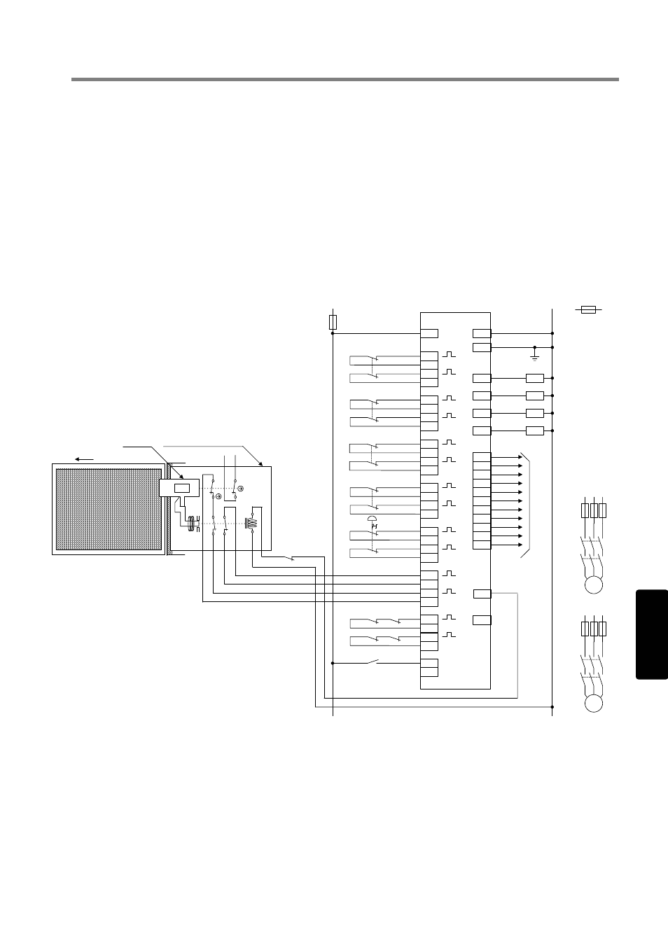
Wiring example (Logic 12b)
In the case where 2 safety switches, enabling switches, 1 emergency stop switch, and 1 interlock switch with
solenoid (spring lock type) are connected.
S1, 3
:Interlock switch
S2, 4
:Enabling switch
S5
:Emergency stop switch
S6
:Interlock switch with solenoid (spring lock type)
S7 :Start
switch
S8
:Solenoid control switch
(Pressing the solenoid control switches after closing the guard door,
contacts 41-42 and 51-52 of S6 turn on, allowing the SafetyOne to restart.)
K1 to 4 :Contactor
M1, 2
:Motor
K1
V+
V-
Y4
Y5
Y6
Y7
Y10
Y11
Y12
Y13
Y14
Y15
Y17
Y20
X0
X1
X2
X3
T0
T1
T2
T3
Y0
Y16
24V DC
0V DC
K2
Y1
K3
Y2
K4
Y3
To
PLC
X5
X6
X7
T5
T6
T7
X10
T10
X4
T4
X11
T11
X12
T12
X13
T13
X14
T14
X15
T15
X16
S7
X17
SafetyOne
FE
S4
K1
K2
K3
K4
S2
S1
S3
S5
Guard open
11
12
51
52
42
A1(-)
A2(+
)
41
S6
21
22
S8
Interlock switch with solenoid
(spring lock type)
Actuator
Fuse
K2
K1
M1
K4
K3
M2