IDEC FS1A Controller User Manual
Page 184
LOGIC
5-136
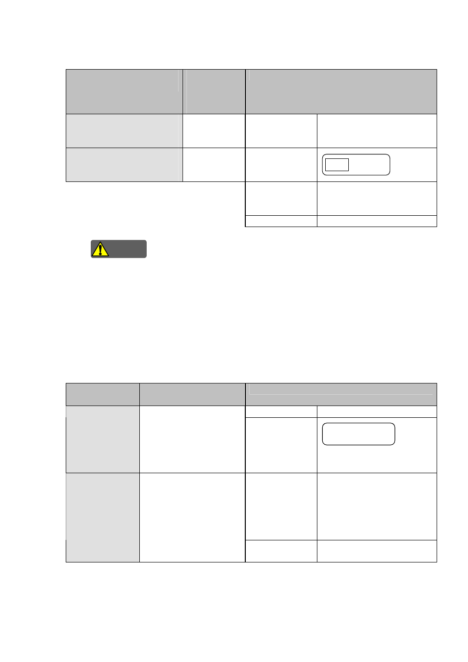
●External device monitor inputs: X14 and X15 (T14 and T15)
External device monitor inputs are used to diagnose status of the devices connected to safety outputs.
Intended inputs
(Terminal names)
Target safety
outputs
(Terminal
names)
Function
External device monitor input 1
(X14-T14)
Safety output 1
(Y0, Y1)
Function name
External device monitor input
External device monitor input 2
(X15-T15)
Safety output 2
(Y2, Y3)
Symbol
External Device
Monitor
EDM
Description
of
operation
This function diagnoses the
status of devices connected to a
target safety output.
Detail
information
Logic
functions
(5-326)
Warning
Safety check signals (pulses signals) are sent from the drive terminals (T14, T15) to diagnose external
devices and monitor circuits. Safety check signals can not be used as a power supply for connected
devices.
Note. If there are unused safety outputs, connect the intended external device monitor terminals (Xn)
to the corresponding drive terminals (Tn). If they are not connected, the SafetyOne detects an
input monitor error. As the result, the error LED displays a “1” and the unit changes to the
Protection state.
●Start inputs: X16 and X17
Start inputs are used to control the start of safety outputs.
Intended inputs
(Terminal names)
Target safety inputs
(Terminal names)
Function
Function name
Monitor input
Start input 1
(X16)
Safety input 1
(X0-T0: TEACH)
Safety input 2
(X2-T2, X3-T3)
Safety input 3
(X4-T4, X5-T5)
Symbol
Single Channel
Monitor
Description of
operation
Safety outputs are started, when
all target safety inputs are in the
safe state and this function is in
the ON state. This function is
turned ON by 0.1s or more ON
operation.
Start input 2
(X17)
Safety input 1
(X1-T0: AUTO)
Safety input 4
(X6-T6, X7-T7)
Safety input 5
(X10, X11)
Safety input 6
(X12-T12, X13-T13)
Detail information
Logic functions (5-325)