Processor – ProSoft Technology MVI56-104S User Manual
Page 152

MVI56-104S ♦ ControlLogix Platform
Reference
IEC 60870-5-104 Server Communication Module
User Manual
Page 152 of 188
ProSoft Technology, Inc.
November 18, 2009
5.4
Data Flow Between the MVI56-104S Module and the ControlLogix
Processor
The following topics describe the flow of data between the ControlLogix
processor, the MVI56-104S module IEC60870-5-104 server, and the remote IEC
60870-5-104 Client unit.
5.4.1 Server
Driver
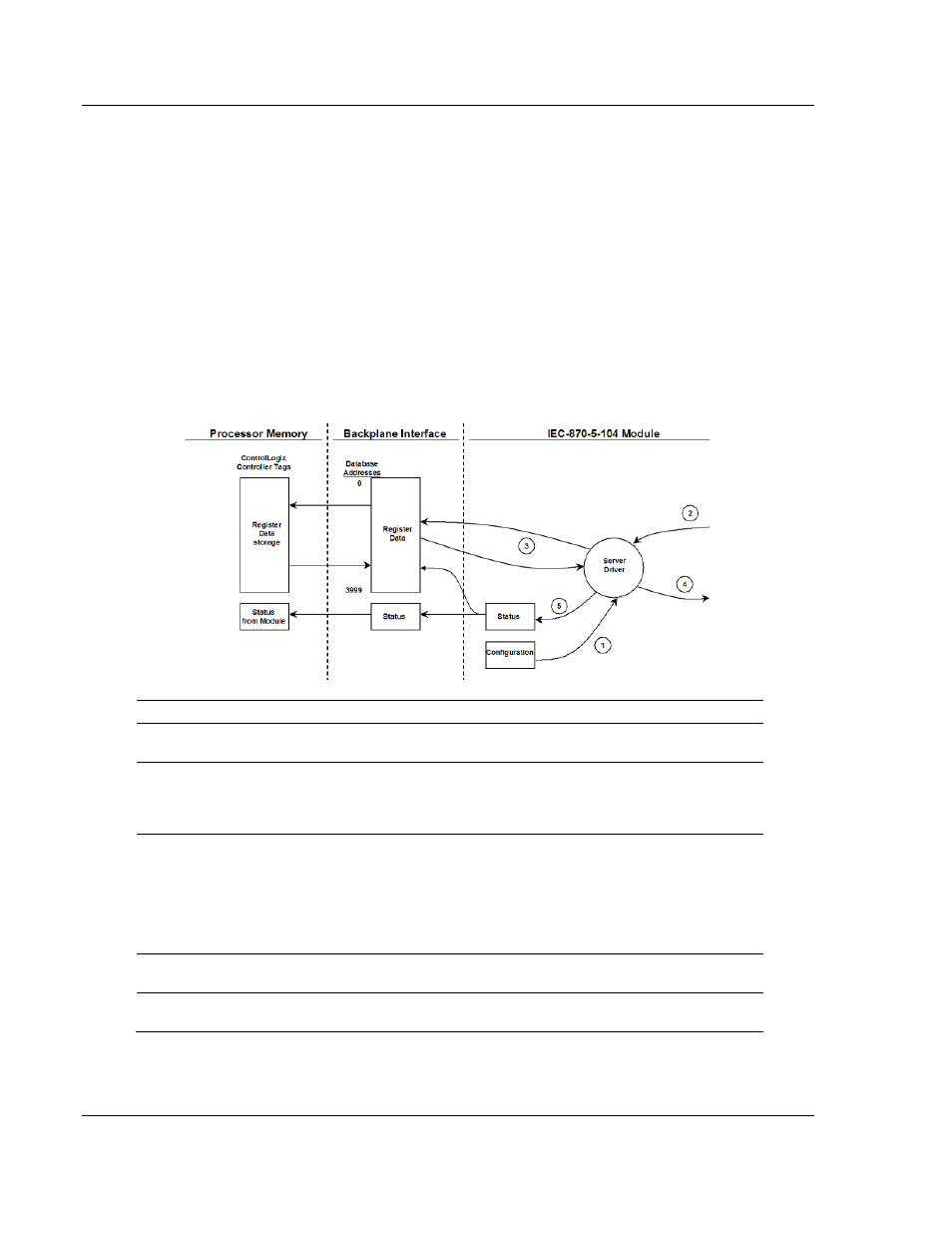
The Server Driver allows the MVI56-104S module to respond to data read and
write commands issued by a client unit on the Ethernet network. The following
flow chart and associated table describe the flow of data into and out of the
module:
Step Description
1
The server driver receives the configuration information from the Compact Flash Disk in
the module. This information configures the driver and define the node characteristics.
2
A Host device issues a read or write command (I-format messages) to the module’s node
address. The driver qualifies the message before accepting it into the module.
Additionally, the host can send S- and U-format messages to the module that will also be
handled by the driver.
3
After the module accepts the message, the data is immediately transferred to or from the
internal database in the module. If the command is a read command, the data is read out
of the database and a response message is built. If the command is a write command,
the data is written directly into the database and a response message is built. The
module will also generate messages without being queried by the host. These messages
include spontaneous and cyclic COT messages. Additionally, the driver may send S- and
U-format messages as required by the user set timeout parameters.
4
After the data processing has been completed in Step 3, the response is issued to the
originating client node.
5
Counters are available in the Status Block that permit the ladder logic program to
determine the level of activity of the Driver.
