3 main logic loop, 4 backplane data transfer – ProSoft Technology MVI56-104S User Manual
Page 146
MVI56-104S ♦ ControlLogix Platform
Reference
IEC 60870-5-104 Server Communication Module
User Manual
Page 146 of 188
ProSoft Technology, Inc.
November 18, 2009
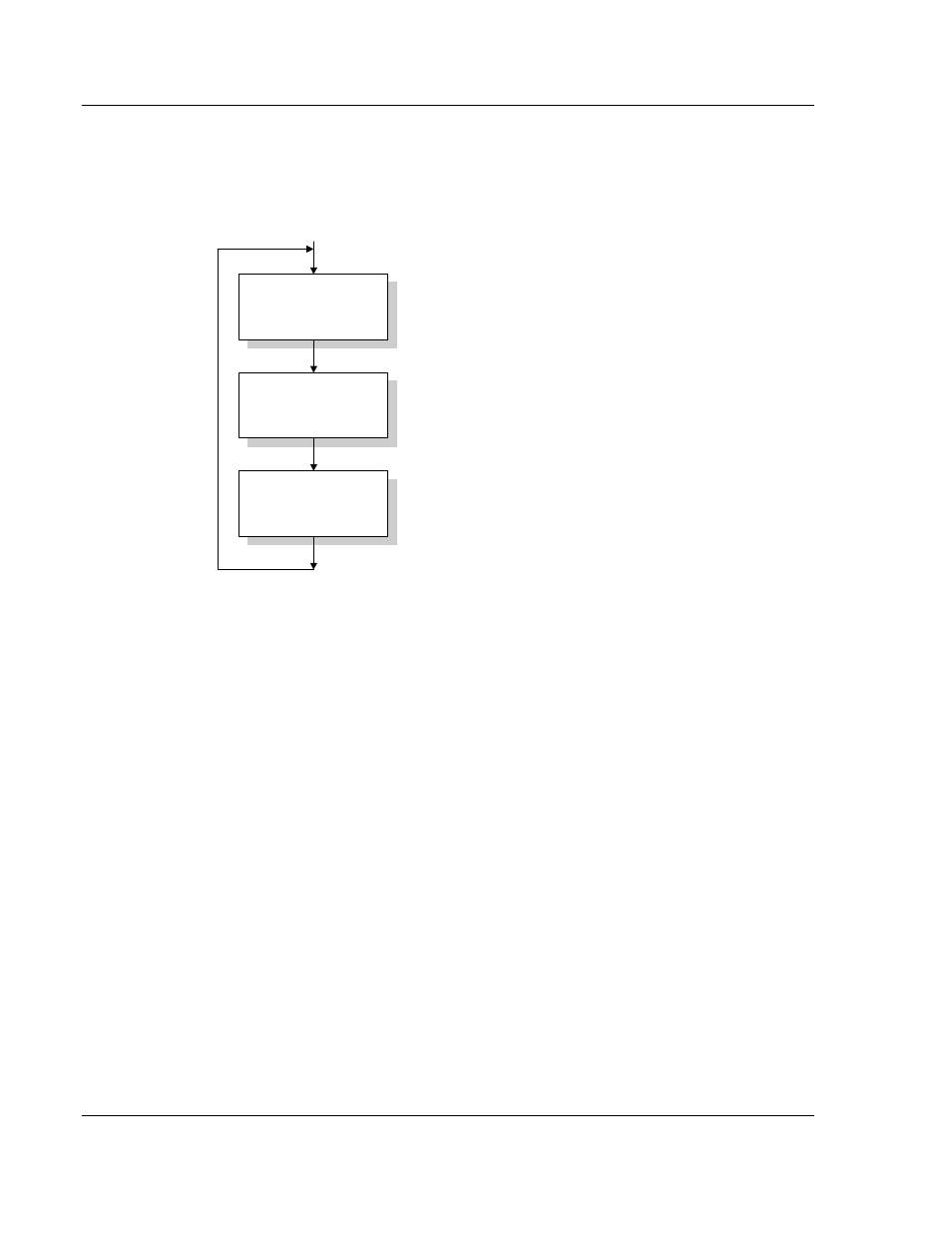
5.3.3 Main Logic Loop
Upon completing the power up configuration process, the module enters an
infinite loop that performs the functions shown in the following diagram.
Call I/O Handler
Call CFG/DEBUG Port
Driver
Call Network Server
Drivers
Call I/O Handler
Transfers data between the module and processor
(user, status, etc.)
Call Serial Port Driver
Rx and Tx buffer routines are interrupt driven. Call to
serial port routines check to see if there is any data
in the buffer, and depending on the value, will either
service the buffer or wait for more characters.
Call Network Server Drivers
Respond to messages received.
From Power Up Logic
5.3.4 Backplane Data Transfer
The MVI56-104S module communicates directly over the ControlLogix
backplane. Data is paged between the module and the ControlLogix processor
across the backplane using the module's input and output images. The update
frequency of the images is determined by the scheduled scan rate defined by the
user for the module and the communication load on the module. Typical updates
are in the range of 1 to 10 milliseconds.
This bi-directional transference of data is accomplished by the module filling in
data in the module's input image to send to the processor. Data in the input
image is placed in the Controller Tags in the processor by the ladder logic. The
input image for the module is set to 250 words. This large data area permits fast
throughput of data between the module and the processor.
The processor inserts data into the module's output image to transfer to the
module. The module's program extracts the data and places it in the module's
internal database. The output image for the module is set to 248 words. This
large data area permits fast throughput of data from the processor to the module.