ProSoft Technology MVI56-104S User Manual
Page 150
MVI56-104S ♦ ControlLogix Platform
Reference
IEC 60870-5-104 Server Communication Module
User Manual
Page 150 of 188
ProSoft Technology, Inc.
November 18, 2009
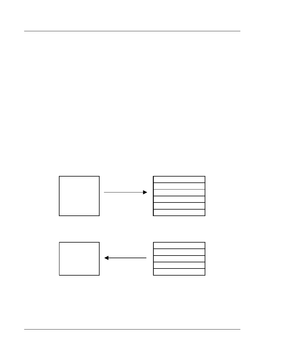
A key concept in interfacing the protocol with the ControlLogix processor is the
relationship between the databases and the data transfer operation between the
module and the processor. The module transfers data to the processor in read
blocks using the input image. These blocks should contain the information
received from the controlling unit (output data) and includes the following data
types: C_SC_NA_1, C_DC_NA_1, C_RC_NA_1, C_SE_NA_1 and C_SE_NB_1.
This data is all sourced from the client unit and passed to the processor for
control. Databases associated with these data types should place the points in
the read data area of the module’s database. The Read Register Start and Read
Register Count parameters in the configuration file establish the portion of the
database to transfer to the processor. Ladder logic extracts the data from the
read data area and places it in the proper location for use by the processor.
Similarly, data to be monitored (input data) by the client unit (all databases
associated with the "M_" data types) must all be placed in the write data area of
the module. The Write Register Start and Write Register Count parameters
establish the portion of the database to receive data from the processor. This
data is read from the processor and passed through the module to the remote
controlling unit. Ladder logic is required to place the data in the correct position in
the write data area. The relationship between the data types and the read and
write data areas is shown in the following diagram:
Write Data
Input Data Types
M_SP_NA_1
M_DP_NA_1
M_ST_NA_1
M_ME_TA_1
M_ME_NB_1
M_IT_NA_1
Read Data
Output Data Types
C_SC_NA_1
C_DC_NA_1
C_RC_NA_1
C_SE_NA_1
C_SE_NB_1
The read and write areas can be placed anywhere in the module’s 4000-word
database area. Because each point is defined individually to the module, the data
for a specific type need not be contiguous in the module’s database. This means
that the module error/status data area can be passed to the controlling station
using the M_ME_NB_1 database. In the database definition for the type,
establish a point for each status value to be monitored by the controlling station
and set the module’s database address for the point in the definition.