2 me-arc remote’s ags-specifi c tech menus – Magnum Energy ME-ARC Remote User Manual
Page 83
Page 76
© 2014 Magnum Energy, Inc.
Using an AGS Module: Operation/Monitoring
Note: The Hour Meter menu’s timer starts when the gen run sense voltage (10-40 volts DC) from
the generator to Pin 2 (+) and Pin 4 (-) is present on the AGS controller.
Info: The 04G Hour Meter menu’s timer can register elapsed time up to 65,000 hours,
and can be reset to “0 Hours” by pressing and holding the SELECT knob for approximately
3 seconds.
Info: The hour meter will not count if the Gen Type DIP switch inside the AGS controller
is set to “2-Wire-Standby” because this setting does not require the gen run sense
voltage from the generator to the AGS.
Info: The CTRL: 03 Gen Control setting has no effect on the whether the hour meter
is active or not.
Info: The gen hours shown in this menu are calculated in the AGS. They do not reset if
the inverter or remote loses power, but they do reset if the AGS controller loses power.
7.2.3.2 ME-ARC Remote’s AGS-specifi c TECH Menus
Press the ME-ARC’s TECH button, and rotate the SELECT knob to access:
TECH: 01 Temperature (rotate SELECT knob until AGS Sensor displays)
• AGS
Sensor – Displays the temperature of the AGS temp sensor plugged into the REMOTE
port on the AGS controller (taken from the METER: 04D AGS Temp display).
TECH: 02 Versions (rotate SELECT knob until AGS displays)
• AGS:
#.# – Displays the software version of the AGS connected to the Magnum network
(displays “0.0” if the remote does not sense an AGS).
TECH: 04 Fault History
Press the SELECT knob, rotate the knob until the 04B AGS Faults menu displays, and then press
the SELECT knob.
• 04B AGS Faults – This menu displays a history of the last nine AGS faults. Information for
each fault displays from the most recent fault (H1) to the earliest/past recorded faults (H2
up to H9).
Note: The 04D Clear Faults menu allows all recorded fault history information—for any in-
verter and/or AGS, ACLD, or PT controller that is network connected—to be cleared/erased.
Refer also to the TECH: 04 Fault History/04D Clear Faults menu in Section 3.2.5.
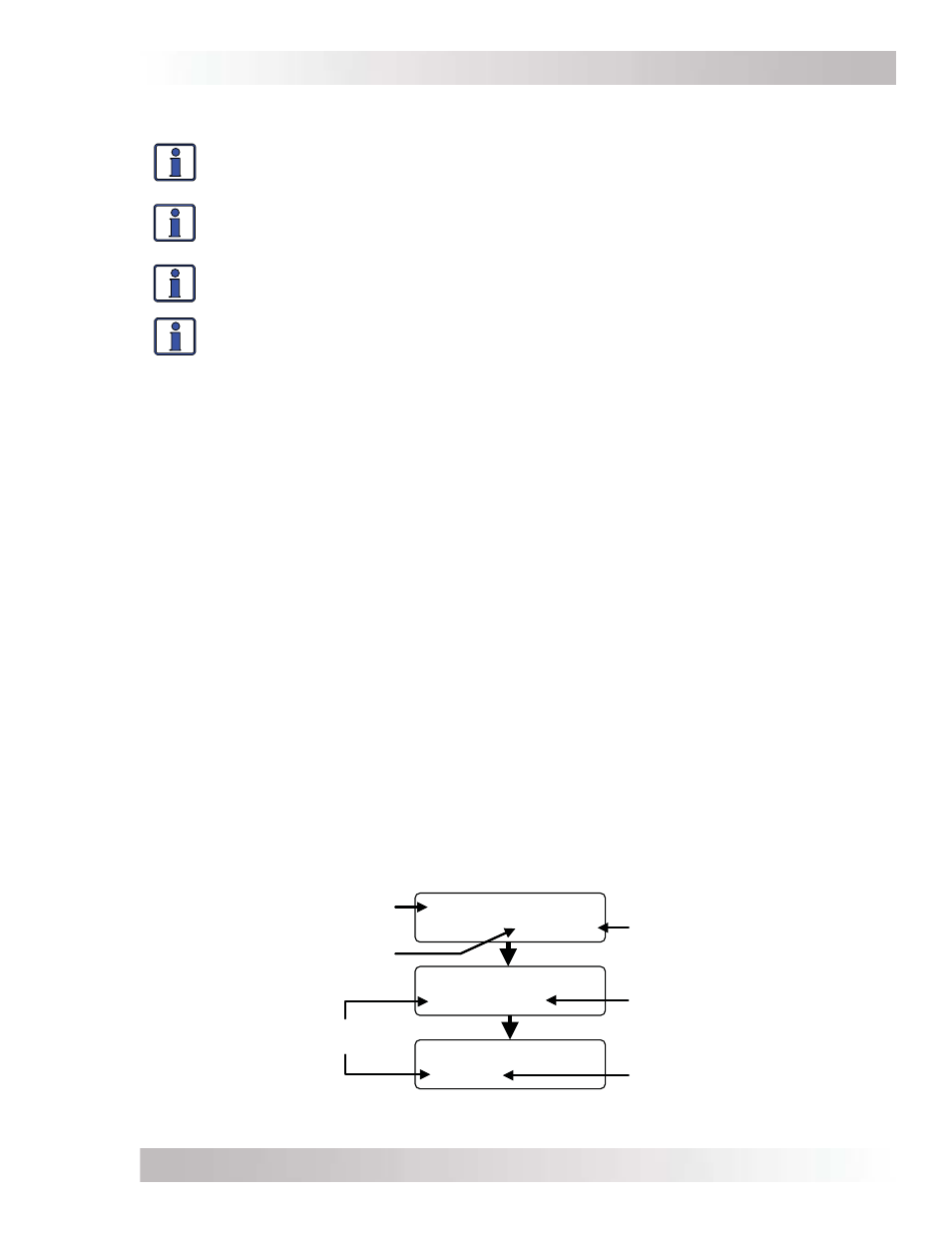
First screen – The top line displays the AGS fault mode. The bottom line displays the fault history
number, day(s) since this fault occurred, and the time this fault occurred.
Rotate the SELECT knob to display the second and third screens for this particular fault.
Second screen – The DC voltage on the AGS at the time of this fault.
Third screen – The temperature of the AGS temp sensor at the time of this fault.
Continue to rotate the SELECT knob to display earlier faults (as applicable).
Time fault
occurred
Fault Temp
H1 D– 1 12:23A
Fault Temp
H1 77F
Fault Temp
H1 14.2 VDC
Fault history
number
Day(s) since
fault occurred
AGS DC voltage
at time of fault
AGS temp
sensor at time
of fault
AGS fault
Figure 7-1, AGS Fault History Screens