0 menu maps: me-arc remote control, Menu maps – Magnum Energy ME-ARC Remote User Manual
Page 47
Page 40
© 2014 Magnum Energy, Inc.
Menu Maps
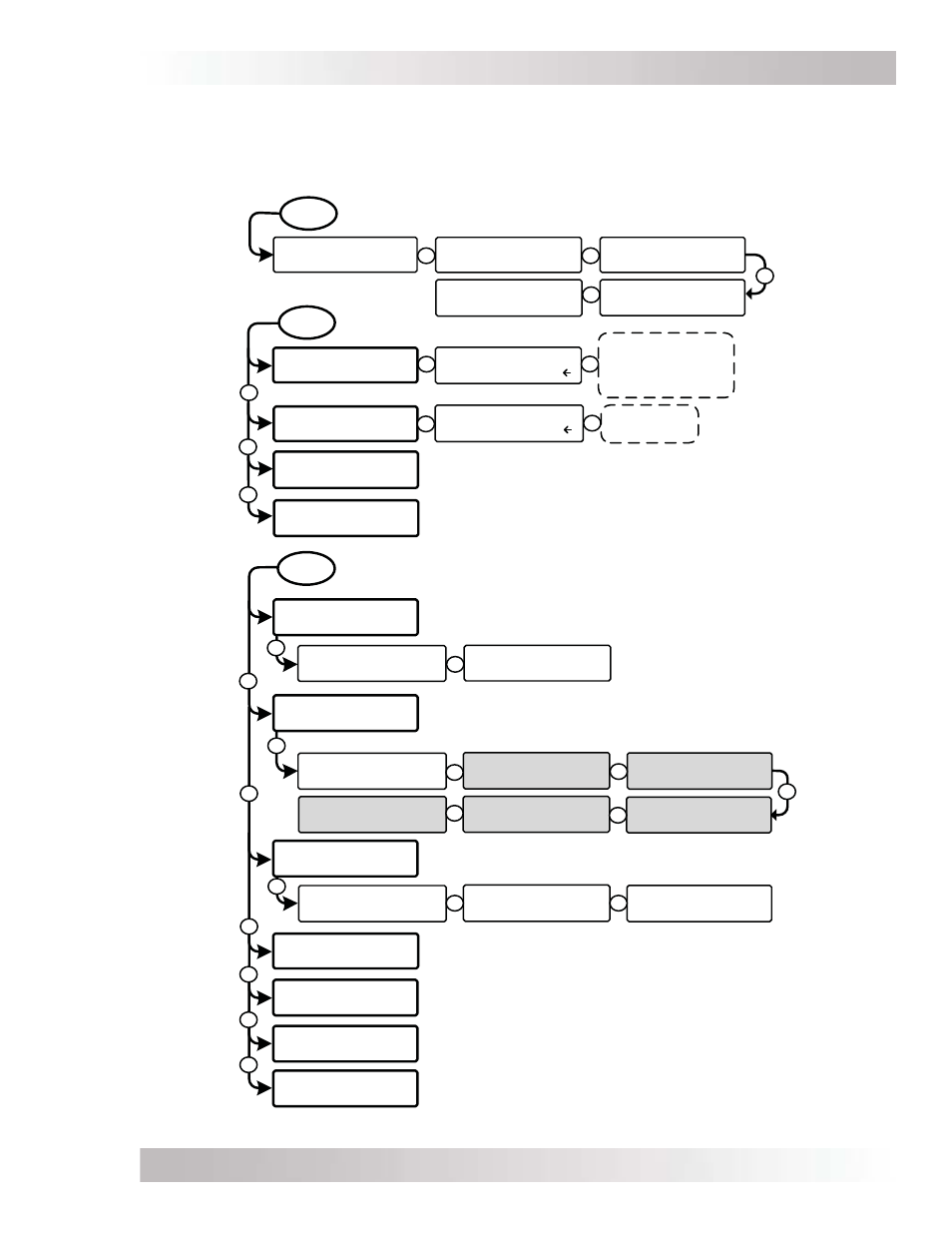
Figure 4-1, FAVS/CTRL/METER Button Menu Maps
Set ACIn Control
Auto Connect
CTRL
03 Gen Control
OFF
04 PT Control
Press SELECT
02 CHG Control
Multi-Stage
Set CHG Control
Multi-Stage
FAVS
F1 Search Watts
5 Watts
F3 AC Input
Amps = 30A
F2 LBCO Setting
20.0 VDC
F4 Battery Type
Flooded
F5 Gen Control
OFF
R
P
R
R
R
R
R
R
Refer to AGS CTRL menu maps in
Section 7.2.5
Refer to PT CTRL menu maps in
Section 10.2.3
01 ACIn Control
Auto Connect
VDC Connect
Time Connect
SOC Connect
ACIn - Disabled
R
Start Float
Start Bulk
R
P
01A DC Volts
14.4 VDC
METER
[Status/Fault]
01 DC Meters
01B DC Amps
-140 Amps
02D Inv/Chg Amps
10 Amps AC
[Status/Fault]
04 AGS Meters
02E Input AC1
120 Volts AC
[Status/Fault]
O5 BMK Meters
Refer to BMK METER menu maps in
Section 8.2.3
Refer to AGS METER menu maps in Section 7.2.5
02F Input AC2
120 Volts AC
P
R
R
R
R
R
R
[Status/Fault]
02 AC Meters
02A AC Output
120 VAC / 60.0Hz
02C Input Amps
30 Amps AC
02B Load Amps
20 Amps AC
P
R
R
[Status/Fault]
03 Timers
03A Charge Time
12.0 Hrs
03C Since EQ
Start 140 Days
03B Since Absorb
Done 003 Days
P
R
R
[Status/Fault]
O6 ACLD Meters
[Status/Fault]
O7 PT Meters
R
R
R
R
Refer to ACLD METER menu maps in
Section 9.2.3
Refer to PT METER menu maps in
Section 10.2.3
Note: Shading denotes screens that only display
with specific Magnum inverter/charger models.
(02B-D = MS-PAE & MSH models, 02E = both MSH
models, 02F = MSH-RE models only)
Read Only displays
4.0
Menu Maps: ME-ARC Remote Control
Figures 4-1 through 4-5 are an overview of the settings and information displays available from
the ME-ARC’s menu buttons. Note: When applicable, battery voltage defaults and ranges are
shown for a 12-volt battery (24-volt systems multiply by 2; 48-volt systems multiply by 4).