SMA SI 3.0-11 User Manual
Page 25
SMA Solar Technology AG
5 Operation of the Sunny Island Inverter With the Sunny Remote Control
Operating Manual
SI30M-44M-60H-80H-BE-en-30
25
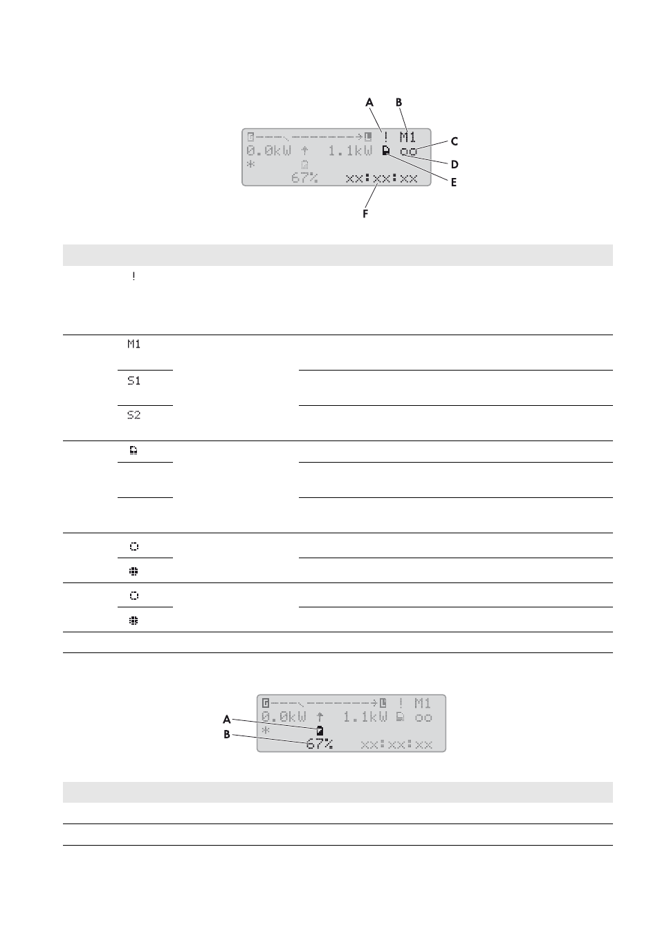
Status of the Sunny Island inverter
Figure 9: Status of the Sunny Island inverter (example)
State of charge of the battery
Figure 10: State of charge of the battery in standard mode (example)
Position Symbol
Designation
Explanation
A
Warning symbol
Symbol for warnings and errors that do not affect the Sunny Island
operation.
If this symbol is flashing, acknowledge the error or warning
B
Device assignment
The Sunny Island connected to the Sunny Remote Control is the
master.
The Sunny Island connected to the Sunny Remote Control is
slave 1.
The Sunny Island connected to the Sunny Remote Control is
slave 2.
C
SD memory card
SD memory card inserted.
Symbol
flashing
The Sunny Island is accessing the SD memory card.
No
symbol
SD memory card not inserted.
D
Multifunction relay 1
Multifunction relay 1 is deactivated.
Multifunction relay 1 is activated.
E
Multifunction relay 2
Multifunction relay 2 is deactivated.
Multifunction relay 2 is activated.
F
hh:mm:ss Time
Off-grid system time
Position Designation
Explanation
A
Battery
Battery symbol
B
State of charge
State of charge of the battery in percent