6 touch probe data management, Introduction – HEIDENHAIN TNC 320 (340 551-01) User Manual
Page 428

428
13 Touch Probe Cycles in the Manual and Electronic Handwheel Modes
13.6 T
o
uc
h Pr
obe D
a
ta Manag
e
ment
13.6 Touch Probe Data Management
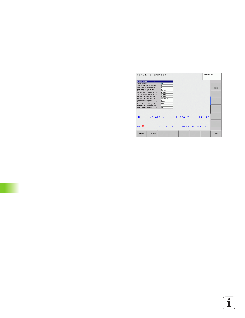
Introduction
To make it possible to cover the widest possible range of applications,
the touch probe management enable offers several settings to enable
you to determine the behavior common to all touch probe cycles: The
TNC always uses the values from the touch probe management, even
it values are also entered in the tool table. Press the PARAMETER soft
key to open the touch probe management window.
Tool number
Number by which the touch probe is registered in the tool table
Infrared/cable probe
0:
Touch probe with cable
1:
Infrared touch probe (machine-dependent function 180° rotation
allowed)
Oriented spindle stop
0:
No oriented spindle stop
1:
Spindle orientation (the touch probe is oriented so that it is always
probed by the same point on the touch probe stylus tip)
Spindle angle
Enter the angle of the touch probe at its home position. This value is
used for spindle orientation during calibration of the ball-tip radius and
for internal calculations (machine-dependent function).
Probe length
Length (ascertained by calibration) by which the TNC offsets the touch
probe dimension
Touch probe radius R
Radius (ascertained by calibration) by which the TNC offsets the touch
probe dimension
Touch probe radius R2
Ball-radius (ascertained by calibration) by which the TNC offsets the
touch probe dimension
Center offset 1
Offset of the touch probe axis to the spindle axis for the reference axis
Center offset 2
Offset of the touch probe axis to the spindle axis for the minor axis
Calibrate angle
Here the TNC enters the orientation angle with which the touch probe
was calibrated
Rapid traverse for measuring
Feed rate at which the touch probe pre-positions, or is positioned
between the measuring points
