3 compensating workpiece misalignment, Introduction, Measuring the basic rotation – HEIDENHAIN TNC 320 (340 551-01) User Manual
Page 420

420
13 Touch Probe Cycles in the Manual and Electronic Handwheel Modes
13.3 Compensating W
o
rk
piece Misalignment
13.3 Compensating Workpiece
Misalignment
Introduction
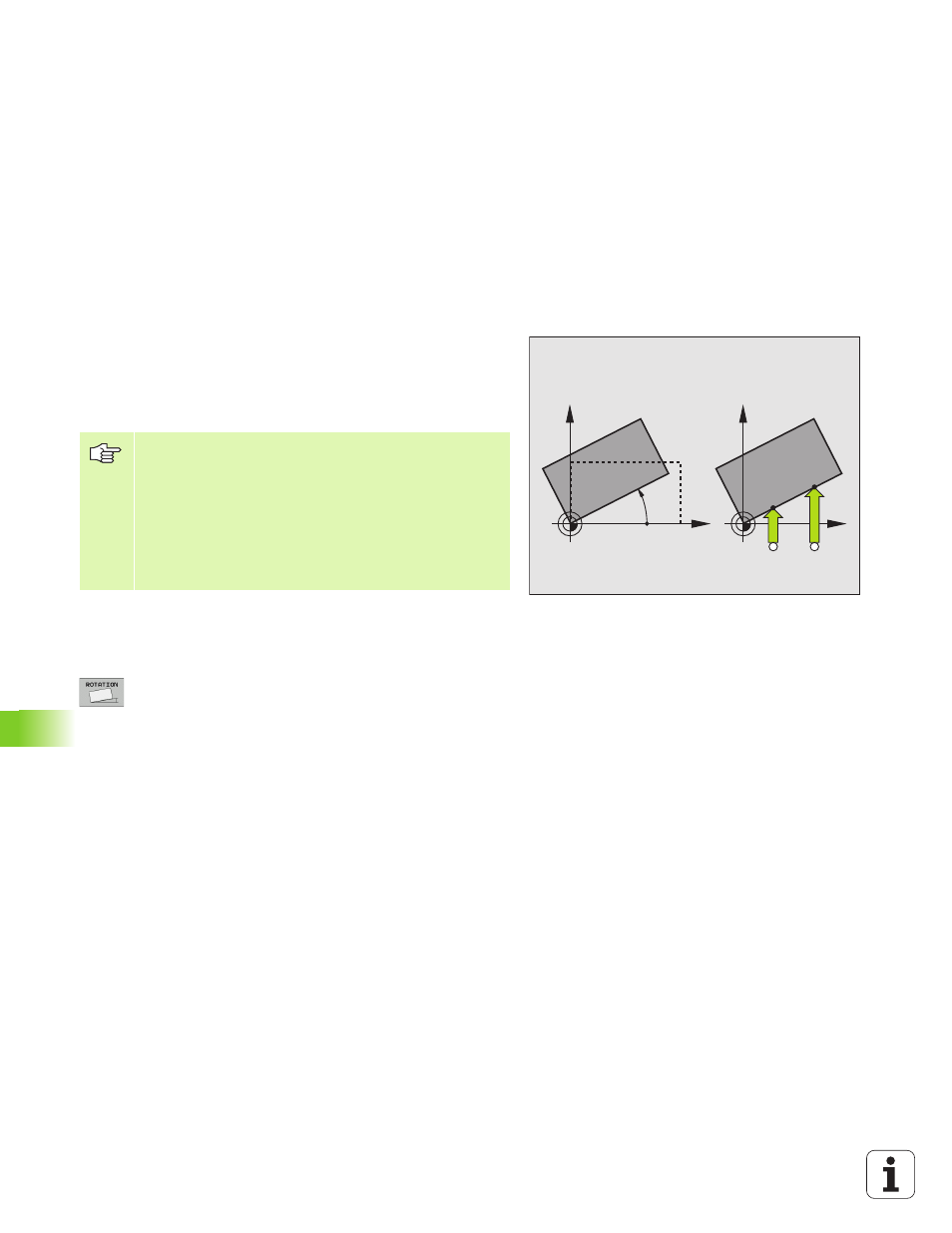
The TNC electronically compensates workpiece misalignment by
computing a “basic rotation.”
For this purpose, the TNC sets the rotation angle to the desired angle
with respect to the reference axis in the working plane. See figure at
right.
Measuring the basic rotation
8
Select the probe function by pressing the PROBING
ROT soft key.
8
Position the ball tip at a starting position near the first
touch point.
8
Select the probe direction perpendicular to the angle
reference axis: Select the axis by soft key.
8
To probe the workpiece, press the machine START
button.
8
Position the ball tip at a starting position near the
second touch point.
8
To probe the workpiece, press the machine START
button. The TNC determines the basic rotation and
displays the angle after the dialog Rotation angle =
X
Y
PA
X
Y
A
B
Select the probe direction perpendicular to the angle
reference axis when measuring workpiece misalignment.
To ensure that the basic rotation is calculated correctly
during program run, program both coordinates of the
working plane in the first positioning block.
You can also use a basic rotation in conjunction with the
PLANE function. In this case, first activate the basic
rotation and then the PLANE function.
