Network requirements, Configuration procedure – H3C Technologies H3C S7500E Series Switches User Manual
Page 165

9-18
After the above configurations are completed, you can monitor all the packets received and sent by
the marketing department and the technical department on the server.
Layer 2 Remote Port Mirroring Configuration Example
Network requirements
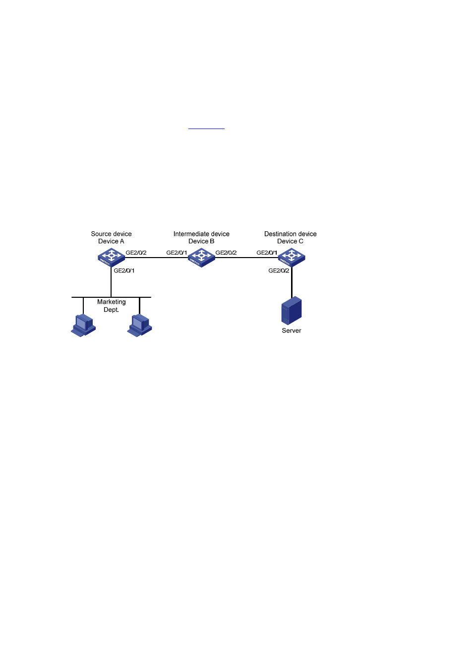
On the Layer 2 network shown in
z
Device A connects to the marketing department through GigabitEthernet 2/0/1, and to the trunk
port GigabitEthernet 2/0/1 of Device B through the trunk port GigabitEthernet 2/0/2; Device C
connects to the server through GigabitEthernet 2/0/2, and to the trunk port GigabitEthernet 2/0/2
of Device B through the trunk port GigabitEthernet 2/0/1.
z
Configure Layer 2 remote port mirroring to enable the server to monitor the bidirectional traffic of
the marketing department.
Figure 9-5 Network diagram for Layer 2 remote port mirroring configuration
Configuration procedure
1) Configure Device A (the source device)
# Create a remote source mirroring group.
[DeviceA] mirroring-group 1 remote-source
# Create VLAN 2.
[DeviceA] vlan 2
[DeviceA-vlan2] quit
# Configure VLAN 2 as the remote probe VLAN of the mirroring group; configure GigabitEthernet 2/0/1
as a mirroring port and GigabitEthernet 2/0/2 as the egress port in the mirroring group.
[DeviceA] mirroring-group 1 remote-probe vlan 2
[DeviceA] mirroring-group 1 mirroring-port gigabitethernet 2/0/1 both
[DeviceA] mirroring-group 1 monitor-egress gigabitethernet 2/0/2
# Configure GigabitEthernet 2/0/2 as a trunk port that permits the packets of VLAN 2 to pass through.
[DeviceA] interface gigabitethernet 2/0/2
[DeviceA-GigabitEthernet2/0/2] port link-type trunk
[DeviceA-GigabitEthernet2/0/2] port trunk permit vlan 2
[DeviceA-GigabitEthernet2/0/2] quit
2) Configure Device B (the intermediate device)
# Configure GigabitEthernet 2/0/1 as a trunk port that permits the packets of VLAN 2 to pass through.
