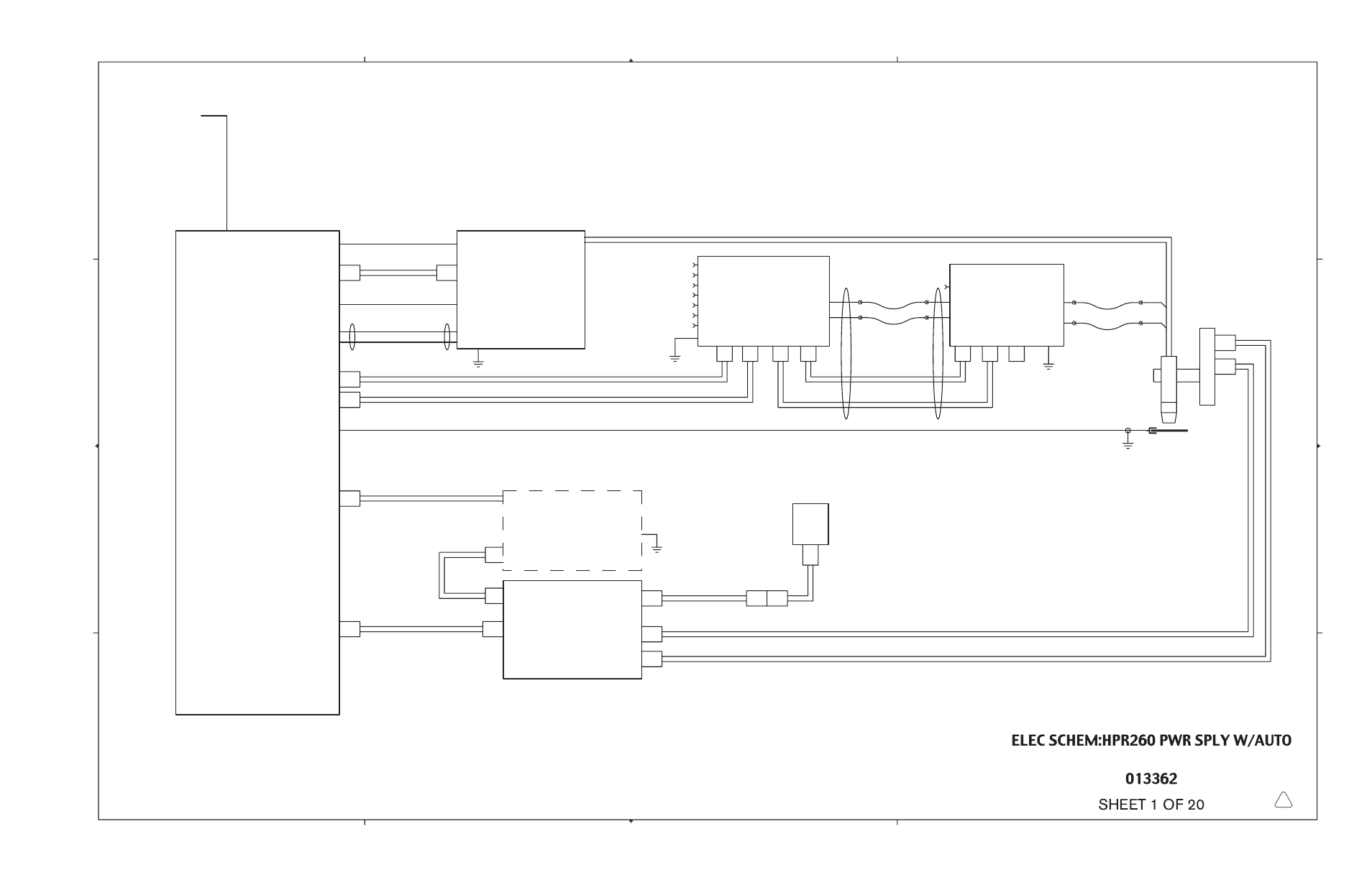
Wiring diagrams -5 – Hypertherm HPR260 Manual Gas Preventive Maintenance Program Rev.5 User Manual
Page 220

7-7
Gas Control Cable
Command
(Optional Unit)
Unit 6
(Customer Supplied)
Interface
CNC Interface Cable
Plasma Interface Cable
1X4
CNC Interface Cable
1X5
1X2
THC
Unit 5
Lifter I/O Interface Cable
Motor Drive Cable
Pendant Ext. Cable
Work Lead
CNC
Power Supply
Unit 1
Gas Power Cable
Ignition Console
2X1
Cooling Return Lead
Cooling Supply Lead
1X1
Pilot Arc Lead
HF/PS Cable
1X3
Unit 2
Negative Supply Lead
Torch
Operator
Pendant
(Optional Unit)
Unit N
Workpiece
Unit M
(Optional Unit)
Torch
Lifter
4X1
Metering Console
Torch Lead Assembly
3X2
3X1
3X4
N2
O2
Air
Selection Console
Unit 3
128930
Power Cable
Cut Gas 2
Cut Gas 1
Atm Vent
Shield
Plasma
Unit 4
72"
3 Phase
w/ Ground
Power
3X3
4X2
4X3
Control Cable
CH4
F5
H35
H5
A
B
C
4
3
2
D
4
3
2
1
A
B
C
1
D
D
5
This manual is related to the following products:
