Error code troubleshooting – 10 of 10 -20 – Hypertherm HPR260 Manual Gas Preventive Maintenance Program Rev.5 User Manual
Page 164
MAINTENANCE
5-20
HPR260 Auto Gas
Instruction Manual
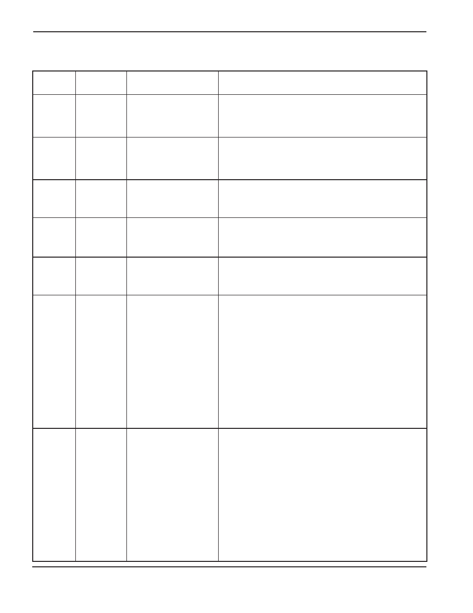
Error code troubleshooting – 10 of 10
Error code
number
Name
Description
Corrective action
144
Internal flash
error
Manual Gas
Only
Communication problem
to the flash chip on
the gas console control
board.
1. Replace the control board.
145
Internal flash
error
Auto Gas
Only
Communication problem
to the flash chip on
the selection console
control board.
1. Replace the control board.
151
Software fail
Software has detected an
incorrect state or
condition.
1. Replace power supply control board.
152
Internal flash
error
Communication problem
to the flash chip on
the power supply control
board.
1. Replace the control board.
153
PS EEPROM
error
EEPROM memory on
power supply control
board not working.
1. Replace the control board.
180
Selection
console CAN
timeout
Auto Gas
Only
The power supply did not
receive a CAN message
from the selection console
within 1 second.
1. Verify that the power supply-to-selection console
CONTROL and POWER cables are not damaged and are
properly connected to PCB3, and the rear of the selection
console.
2. Verify that D17 (+5 VDC) and D18 (+3.3 VDC) are
illuminated on PCB2 inside the selection console. These
LEDs indicate power to PCB2. Also verify that D26 (CAN -
RX) and D27 (CAN - TX) are illuminated on PCB2 inside
the selection console. These LEDs indicate communication
between the selection console and the power supply.
3. If power is present at PCB2 and PCB3 and both selection
console cables are good, then PCB2 or PCB3 has failed.
Use the CAN tester to verify which board needs to be
replaced.
181
Metering
console CAN
timeout
Auto Gas
Only
The power supply did not
receive a CAN message
from the metering console
within 1 second.
1. Verify that the power supply-to-metering console
CONTROL and POWER cables are not damaged and are
properly connected to PCB3, and the rear of the metering
console.
2. Verify that D17 (+5 VDC) and D18 (+3.3 VDC) are
illuminated on PCB2 inside the metering console. These
LEDs indicate power to PCB2. Also verify that D26 (CAN -
RX) and D27 (CAN - TX) are illuminated on PCB2 inside
the metering console. These LEDs indicate communication
between the metering console and the power supply.
3. If power is present at PCB2 and PCB3 and both metering
console cables are good, then PCB2 or PCB3 has failed.
Use the CAN tester to verify which board needs to be
replaced.
5