Chapter 6. remote control, 1 introduction, 1 rs-485 – Comtech EF Data CSAT-5060 User Manual
Page 53: 2 rs-232, Rs-485, Rs-232
6–1
Chapter 6. REMOTE CONTROL
6.1 Introduction
This document describes the protocol and message repertoire for remote monitor and
control of the CSAT outdoor terminal.
The electrical interface is either an RS-485 multi-drop bus (for the control of many
devices) or an RS-232 connection (for the control of a single device), and data is
transmitted in asynchronous serial form, using ASCII characters. Control and status
information is transmitted in packets, of variable length, in accordance with the structure
and protocol defined in later sections.
6.1.1
RS-485
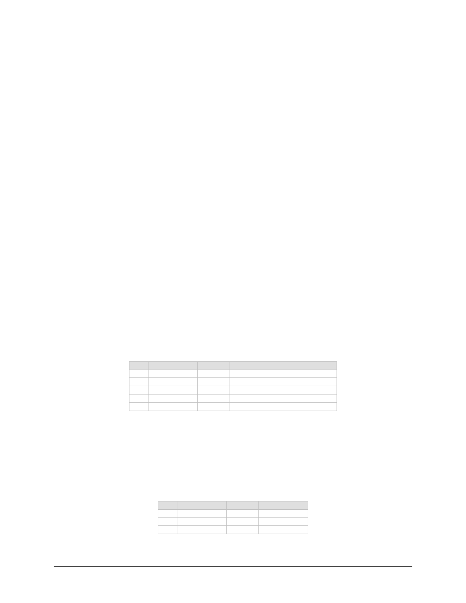
The RS-485 interface is provided at the 19-pin circular J5 connector. The interface is a
4-wire RS-485 interface using the pin out shown in the table below. Since a half-duplex
communication protocol is used, the +Tx and +Rx as well as the –Tx and –Rx signals can
be tied together at the user end to support a 2-wire interface. The RS-485 driver is only
active during transmission and is tri-stated when not is use
.
Table 6-1. RS-485 Interface
Pin
Signal Name
I/O
Notes
A
RS-485 +Rx
Input
CSAT Receive line
B
RS-485 –Rx
Input
CSAT Receive line complement
C
RS-485 +Tx
Output
CSAT Transmit line
D
RS-485 –Tx
Output
CSAT Transmit line complement
T Ground
Passive
6.1.2
RS-232
The RS-232 interface is provided at the 19-pin circular J5 connector. The interface
provides the five signals shown in the table below. The CSAT only requires three wires
(TD, RD and Ground), the other two signals are provided for terminal equipment that
requires RTS/CTS handshaking. The CSAT simply ties these two signals together.
Table 6-2. RS-232 interface
Pin
Signal Name
I/O
Notes
E
RS-232 RD
Input
CSAT Rx line
G
RS-232 TD
Output
CSAT Tx line
T Ground
Passive