A.5 redundancy installation – Comtech EF Data CSAT-5060 User Manual
Page 110
C-Band Transceiver
Revision 1
CSAT-5060 5 to 25 Watt Installation
MN/CSAT5060.IOM
A–20
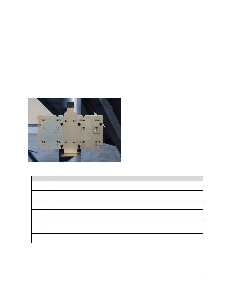
A.5
Redundancy Installation
Notes:
1. Redundant CSAT’s require two AS/0414 pole mount kits. Refer to A.2, Single-
Thread Installation, for AS/0414 installation instructions.
2. After the two pole brackets have been attached to the pole, they need to be properly
spaced in relation to each other. This spacing is established with the switch-
mounting bracket (1, figure A-2).
Step
Procedures
1
Center the bracket (1, figure A-2) horizontally on the top Unistrut bracket
and fasten with two bolts (8) flat washers (5), and split washers (6).
2
Loosen lower Unistrut bracket and position so the lower holes in the bracket are aligned
vertically with the center of the lower Unistrut bracket.
3
Position the springnuts as required. Secure bracket (1) to the Unistrut bracket using two
bolts (8), flat washers (5), and split washers (6). Tighten the tension bracket.
4
Install mounting brackets on each side of bracket (1) in accordance with A-2, Single-Thread
instructions.
5
Place a unit on each mounting bracket and secure with four bolts.
6
Position assembled switch (1, figure A-18) on bracket (1, figure A-15) and secure with two
screws (4), flat washers (5), and lock washers (6).
7
Position switch box (1, figure A-17) on bracket (1, figure A-15). Secure with four bolts
(7, figure A-15), four flat washers (12) and four lock washers (8).
Figure A-21. Installation of the
Redundant Brackets