Chp05 connector pinouts, Chapter 5. connector pinouts – Comtech EF Data CDM-700 User Manual
Page 47
5–1
Chapter 5. CONNECTOR PINOUTS
5.1
External Connections
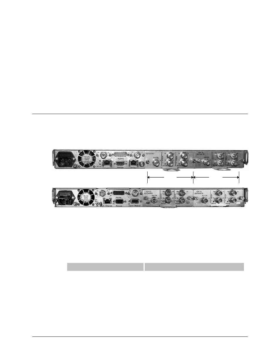
External cables are attached to connectors on the rear panel of the CDM-700. Figure 5-1 shows
the CDM-700 rear panel – both current and original chassis configurations – with typical data
interfaces installed in Slot 1 and Slot 2.
Chassis – Initially Released Version
(70/140 MHz shown)
Chassis – Rev. A or Later Versions
(70/140 MHz shown
)
Figure 5-1. CDM-700 Chassis – Rear Panel
Refer to the applicable appendix in this manual for specific Data Interface pinout information.
The initially released chassis differs from the Rev. A chassis as follows:
Chassis – Initially Released Version
Chassis – Rev. A and Later Production Version
J6: RJ-45, SerDes
J7: SMA-F, External Input
J6: 9 Pin D-F, Async Channel
J7: BNC-F, External Input
For support of 1:1 and 1:N operation, a Rev. A or later chassis is required.
Slot 1
Slot 2
- CDD-880 (124 pages)
- CDM-800 (130 pages)
- ODMR-840 (184 pages)
- CDM-750 (302 pages)
- CDM-840 (244 pages)
- SLM-5650A (420 pages)
- CTOG-250 (236 pages)
- CDM-760 (416 pages)
- CDM-710G (246 pages)
- CDM-600/600L (278 pages)
- CDMR-570L (512 pages)
- CDM-625 (684 pages)
- CDM-625A (756 pages)
- CDD-564A (240 pages)
- CDD-564L (254 pages)
- CLO-10 (134 pages)
- MCED-100 (96 pages)
- CDMR-570AL (618 pages)
- CDM-600 LDPC (2 pages)
- BUC Power Supply Ground Cable (2 pages)
- MPP70 Hardware Kit for CDM-570L (4 pages)
- MPP50 Hardware Kit for CDM-570L (4 pages)
- CDM-625 DC-AC Conversion (4 pages)
- CDM-625 DC-AC Conversion with IP Packet Processor (4 pages)
- DMDVR20 LBST Rev 1.1 (117 pages)
- DMD2050E (212 pages)
- DMD-2050 (342 pages)
- DMD1050 (188 pages)
- OM20 (220 pages)
- QAM256 (87 pages)
- DD240XR Rev Е (121 pages)
- MM200 ASI Field (5 pages)
- DM240-DVB (196 pages)
- MM200 (192 pages)
- CRS-150 (78 pages)
- CRS-280L (64 pages)
- CRS-170A (172 pages)
- CRS-180 (136 pages)
- SMS-301 (124 pages)
- CiM-25/8000 (186 pages)
- CiM-25 (26 pages)
- CRS-500 (218 pages)
- CRS-311 (196 pages)
- CIC-20 LVDS to HSSI (26 pages)