Comtech EF Data CDM-700 User Manual
Page 28
CDM-700 High Speed Satellite Modem
Revision 5
Introduction
MN/CDM700.IOM
CRS-170A and CRS-180 support 1:1 redundancy for the L-Band and 70/140 MHz, respectively.
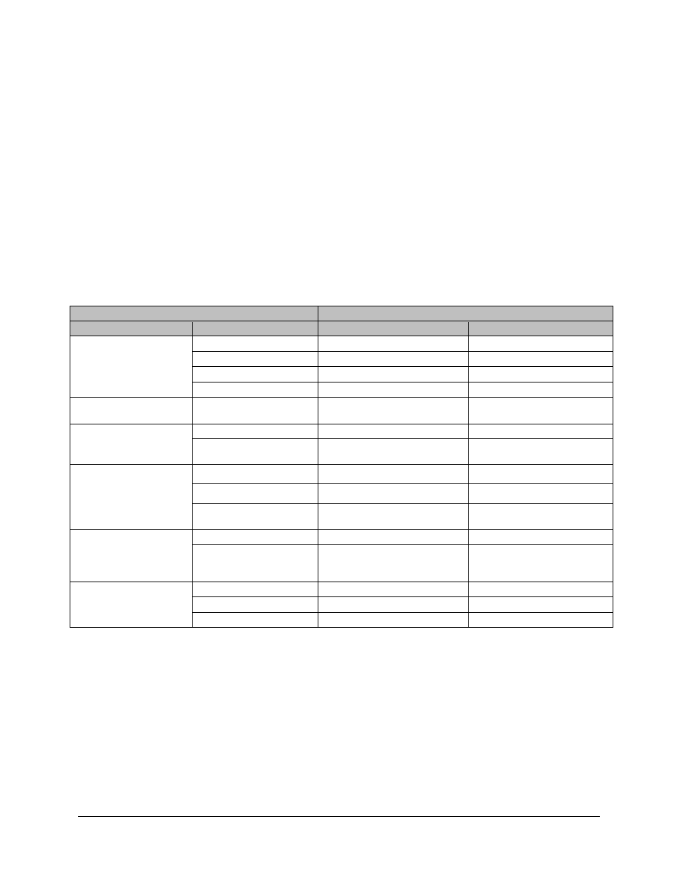
the CRS-300 provides support for 1:N redundancy:
1:1 Redundancy with the CRS-170A (70/140 MHz) and CRS-180 (L-Band):
The Allowable
CDM-700 Modem Configuration
column of the table below shows the data interface combinations
of the CDM-700 that are supported by the CRS-170A and CRS-180. First, the 1:1 switch is selected
depending upon the operating frequency, and then a data interface kit for Slot 1 and Slot 2 is
chosen. More information on these kits is provided in the datasheet and manual for CRS-170A or
CRS-180 1:1 Redundancy Switches.
1:N Redundancy with the CRS-300: The CRS-300 was originally designed for operation with the
CDM-600 and subsequently adapted to a number of other modems. It is capable of supporting
interfaces up to the point where there are no more paths left to route traffic. This is the reason why
the CRS-300 supports a limited set of the interface combinations supported by the CDM-700.
Allowable CDM-700 Combinations
1:N CRS-300 Configurations
Slot 1
Slot 2
TMI Module
Notes 1,3
RMI Module
Notes 2,4
Dual G.703 (CDI-10)
None CRS-345 CRS-306
Dual G.703 (CDI-10)
CRS-345
CRS-306
HSSI (CDI-60)
Not Supported
Not Supported
GigE (CDI-70)
CRS-345, Wired-Around Only
CRS-306, Wired-Around Only
OC3 Optical (CDI-50-1)
Single Mode
None
Not Supported
Not Supported
OC3 Copper (CDI-50-1)
None CRS-325 CRS-306
GigE (CDI-70) (Allowed
in Standby unit only)
CRS-325 CRS-306
HSSI (CDI-60)
None CRS-336 CRS-306
HSSI (CDI-60
Not Supported
Not Supported
GigE (CDI-70)
CRS-336, CDI-70 is
Wired-Around Only
CRS-306, CDI-70 is
Wired-Around Only
GigE (CDI-70)
None CRS-336 CRS-306
GigE (CDI-70)
Note 5
CRS-336, One CDI-70 is
Wired-Through and the other
is Wired-Around
CRS-306, One CDI-70 is
Wired-Through and the other
is Wired-Around
None
Dual G.703 (CDI-10)
CRS-345
CRS-306
HSSI (CDI-60)
CRS-336
CRS-306
GigE (CDI-70)
CRS-336
CRS-306
Refer to the CRS-300 1:10 Redundancy Switch Installation and Operation Manual for additional
details and operational information.
Notes:
1. A TMI (Traffic Modem Interface) Module is used with each Primary Traffic Modem.
2. An RMI (Redundant Modem Interface) Module is used with the Standby Modem.
3. As of April 2007, GigE or HSSI TMI requires a CRS-336. The CRS-336 fully replaces or
spares a CRS-335.
4. As of April 2007, the CRS-306 supersedes the CRS-305.
5. One Slot with a CDI-70 will support the maximum data rate. The 2
nd
slot is needed only
for the Standby Modem
1–4