AMETEK Lx Series II User Manual
Page 79
User Manual
Lx / Ls Series II
75
4.2.4 PROGRAM Menu
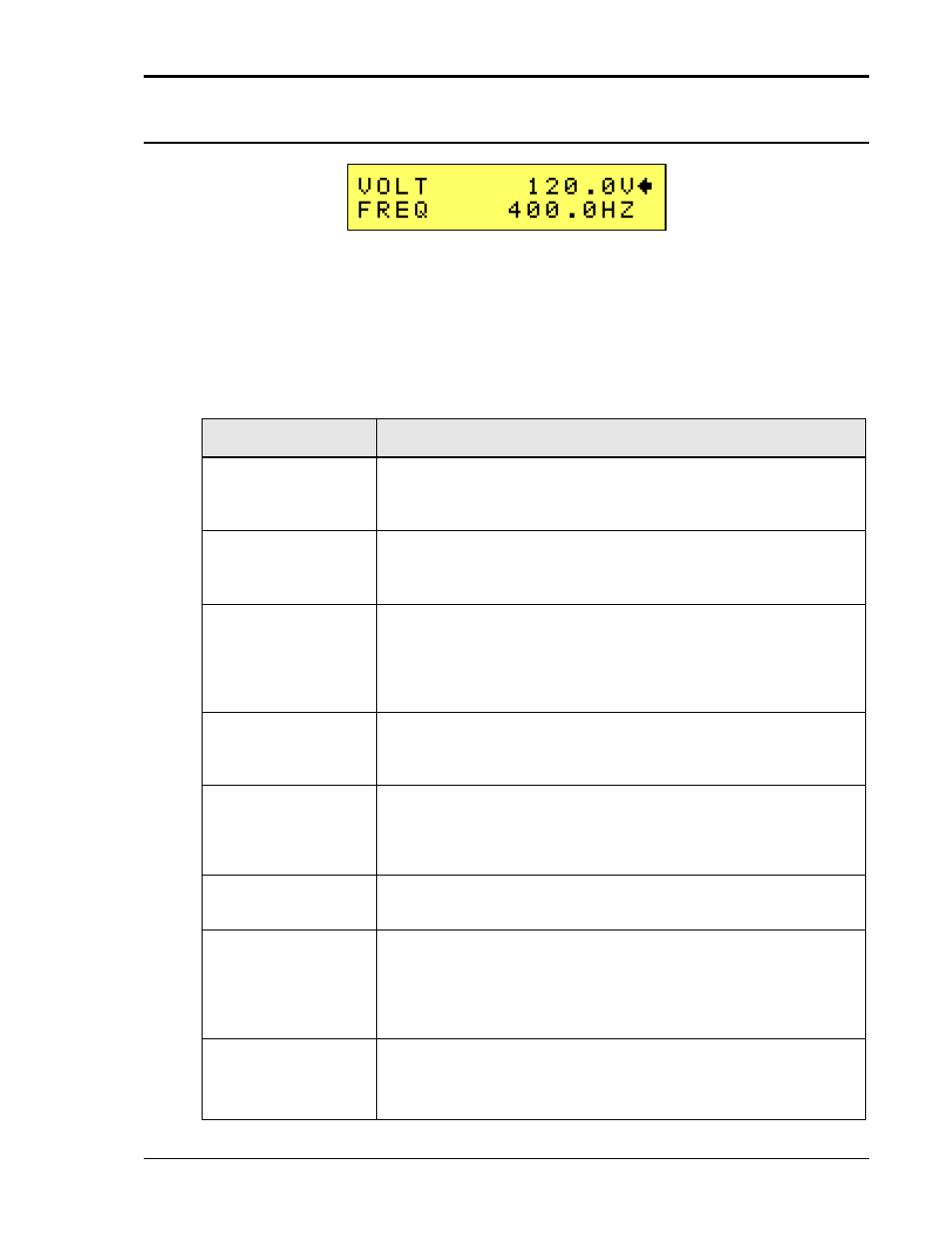
Figure 4-4: PROGRAM Menu
The PROGRAM menu is shown in Figure 4-4. It can be reached in one of two ways:
1. by selecting the Menu key, selecting the PROGRAM entry and pressing the Enter key.
2. by pressing the Set key.
The PROGRAM menu is used to change primary output parameters. Less frequently used
parameters are located in the CONTROL menu.
The following choices are available in the PROGRAM menus:
ENTRY
DESCRIPTION
VOLTAGE
Programs the output voltage in Vrms. The voltage can be changed
from 0 to its max range value as determined by the configuration
settings and the selected voltage range using the Voltage shuttle.
FREQ
Programs the output frequency The frequency can be changed from
its min to its max value as determined by the configuration settings
using the Frequency shuttle.
VRANGE
Selects 150V or 300V voltage range (if available). The actual range
values may be different depending on the configuration. The value of
this field can be changed with either Voltage or Frequency shuttle as
long as the active pointer () points to the VRANGE entry. If only
one voltage range is available, this field cannot be changed.
PHASE
Selects the phase angle between the external clock and the output
of the AC source. If the clock source is internal, this parameter has
no effect.
FUNC
Selects the waveform for the selected phase. Available choices are
SINE, SQUARE and CLIPPED or any user defined waveform that
was downloaded to the AC source waveform memory using the
IEEE-488, LAN, RS232C or USB interface.
CLIP LEVEL
Sets the clip level for the CLIPPED sine wave in percent VTHD. The
range is 0 to 20 %.
CURR
Sets the current limit value for the current detection system. When
the load current value exceeds the set current limit, a fault condition
is generated. The actual response of the AC Source to a current limit
fault is determined by the protection mode selected in the OL MODE
field. (CC = Constant Current, CV = Constant Voltage).
OL MODE
Sets the current limit over load mode. The actual response of the AC
Source to a current limit fault is determined by this setting. Available
settings are CC for Constant Current mode or CV for Constant
Voltage mode. In CV mode, the AC source output will trip off and