Non-routine output gain, Calibration – AMETEK Lx Series II User Manual
Page 116
User Manual
Lx / Ls Series II
112
6.6 Non-Routine Output Gain Calibration
If the Current Limit board assembly (P/N 7004-703-1) is replaced in the field or one of the
amplifiers has been replaced, it is necessary to check the gain of each phase and adjust as
needed.
WARNING:
This requires the top cover to be removed and should be done by qualified service
personnel only. Dangerous Voltages are present inside the AC power source.
To adjust amplifier output gains, proceed as follows:
1. Turn OFF the front panel circuit breaker.
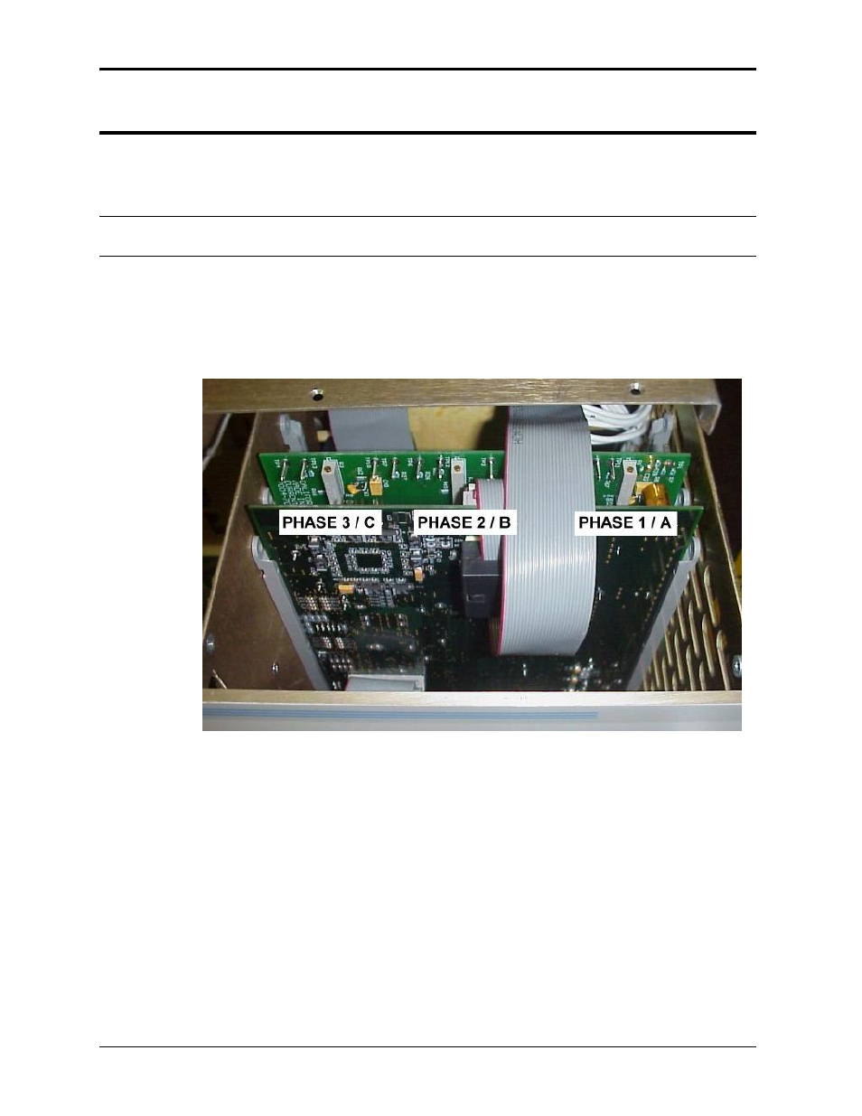
2. Loosen the top cover and slide back until the Current Limit board assembly (P/N 7004-
703-1) is uncovered. This is the vertical board directly behind the CPU/Controller board.
Refer to Figure 6-1.
Figure 6-1: Location of Gain pot adjustments and TP1 through TP4
3. Go to the Output Calibration screen by repeatedly pressing the MENU key until OUTP
CAL is displayed.
4. Select this function by pressing the cursor until the arrow on the right side of the display
point to OUTP CAL. Press the ENTER key.
5. A Calibration Password (CAL PWORD) will be required. The password will be the value
of the high voltage range. Enter this value with the Front Panel encoder and press the
ENTER key.
6. Select Phase A and check the output calibration coefficient setting. The value should be
450 for both standard Ls/Lx models and for Lx/Ls models with the
–HF (high frequency)
option. (Refer to table below). If not, adjust as needed and press the ENTER key.
7. Select Phase B and check for the correct value or set it as needed.