AMETEK Lx Series II User Manual
Page 59
User Manual
Lx / Ls Series II
55
3.6.7 System Interface Connectors
– MASTER and AUXILIARY
WARNING: The system interface connectors are for use with AMETEK supplied
cables, and only between California Instruments equipment.
A set of two System Interface connectors is located on the rear panel of each 4500Lx/Ls chassis.
The system interface is used to connect the multiple 4500Lx/Ls or 6000Lx/Ls power sources in a
Master/Auxiliary configuration to create a 9000Lx/Ls/2, 12000Lx/Ls/2, 13500Lx/Ls/3 or
18000Lx/Ls/3 AC power source configuration. In this configuration, only the Master power
source has a built-in controller and front panel. The System Interface cable provided in the Lx or
Ls Series ship kit (CI P/N 250778) MUST be used to connect both chassis as shown in Figure
3-3.
Note that no user accessible signals are provided on the System Interface connections and they
should only be used for their intended purpose. To use the System Interface capability, the
output safety cover has to be removed. As such, multi-chassis configurations cannot be used
outside of a cabinet with proper rear screens.
Note that for multi-chassis systems, it is recommended to turn the Master unit ON first and then
the Auxiliary unit(s). To turn the system off, turn OFF the Auxiliary unit(s) first and then the
Master unit.
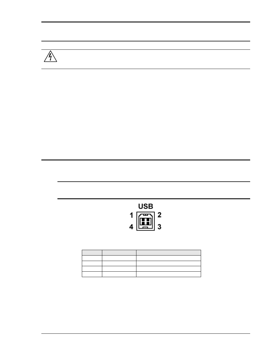
3.6.8 USB Interface
A standard USB Series B device connector is located on the rear panel for remote control. A
standard USB cable between the AC Source and a PC or USB Hub may be used.
Note: Use of the USB port to control more than one power source from a single PC is
not recommended, as communication may not be reliable. Use GPIB interface for
multiple power source control.
Figure 3-6: USB Connector pin orientation.
Pin
Name
Description
1
VBUS
+5 VDC
2
D-
Data -
3
D+
Data +
4
GND
Ground
Table 3-9: USB Connector pin out.