AMETEK Lx Series II User Manual
Page 119
User Manual
Lx / Ls Series II
115
6.8 Non-Routine Amplifier Load Balance Adjustment
This procedure is required for all versions of the power source, single and multibox if an amplifier
has been replaced or two or more units are combined into a multi-box system.
If this is a multi-box power system you must first check the Master source. After the Master
source is checked attach the Auxiliary unit and check each amplifier by measuring the voltage at
the respective test points (TP2 throug TP4) on the Current Limit board assembly (P/N 7004-703-
1) in the auxiliary source. Compare the voltage at each test point with that at TP2 of the Master
source.
This procedure requires a load to be applied to the power source. See section
To adjust amplifier load balance, proceed as follows:
1. Connect a 10 milliohm current shunt to the Neutral or Common output terminal of the
power source. Connect the AC DVM to the shunt monitor terminals.
2. Apply one terminal of the load to the other side of the current shunt. Connect the other
terminal of the load to the Phase A output terminal.
3. Program the power source to the 1-phase mode, 60 Hz and 100 Volts RMS on the low
voltage range. Apply a load value that represents 80% of the maximum current allowed.
4. Close the output relay.
5. Check the voltage at TP2 of the Master power source. Record this value.
6. Check the voltages at TP3 and TP4 of each power source in the system. Verify the
voltage at each test point is within 0.02 vrms of the TP2 of the Master power source.
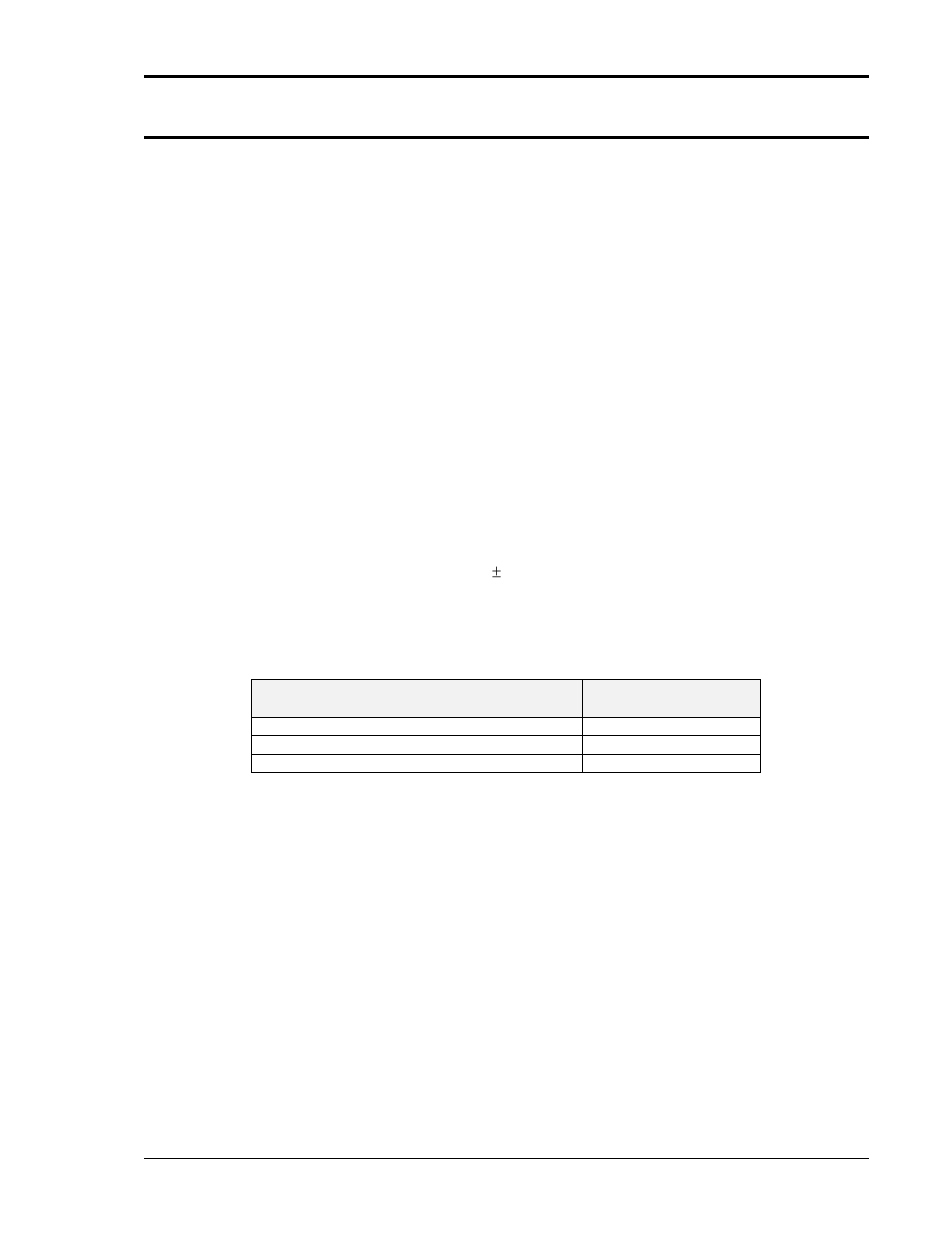
7. If the voltage is not within this tolerance adjust the Amplifier Regulation adjustment (R1)
on the corresponding amplifier. Refer to the table below for the correct adjustment.
8. Check the Load Balance at 400 Hz and the highest frequency allowed. Make sure the
voltage at the test points do not differ by more than 0.2 volts rms.
Test Point on Current Limit Board
ADJUSTMENT
R1 on Amplifier
TP2 of Aux Source
Phase A (A1)
TP3 of Aux Source
Phase B (A2)
TP4 of Aux Source
Phase C (A3)