7 “non-routine amplifier gain balance adjustment – AMETEK Lx Series II User Manual
Page 118
User Manual
Lx / Ls Series II
114
6.7 Non-Routine Amplifier Gain Balance Adjustment
If an amplifier has been replaced on Lx/Ls models that have single-phase mode, it will be
necessary to check the amplifier gain balance and adjust it if needed. For single box Ls-3 models
(no single phase mode), this adjustment is not required.
If two or more Lx/Ls units are combined into a multi-box system, the gain of all amplifiers has to
be matched to each other. For systems purchased with the
–MB option, this was done at the
factory. For units purchased without this option, the gain balance should be checked. If units
have different gains, the AC input circuit breaker of one of the units combined may trip due to
bus pump up. Matching the gains of the amplifiers that are paralleled will prevent this.
This procedure requires the power sources to be connected using the system interface cable.
This cable (CI P/N 250778) is supplied with the
–MB option. If not available, it can be obtained
through AMETEK Programmable Power customer service.
WARNING:
This requires the top cover to be removed and should be done by qualified service
personnel only. Dangerous Voltages are present inside the AC power source.
To adjust amplifier gain balance, proceed as follows:
1. Remove all loads from the output.
2. Program the output to the 1-phase mode and 400 Hz.
3. Program the output voltage to 100 volts on the low voltage range with ALC off.
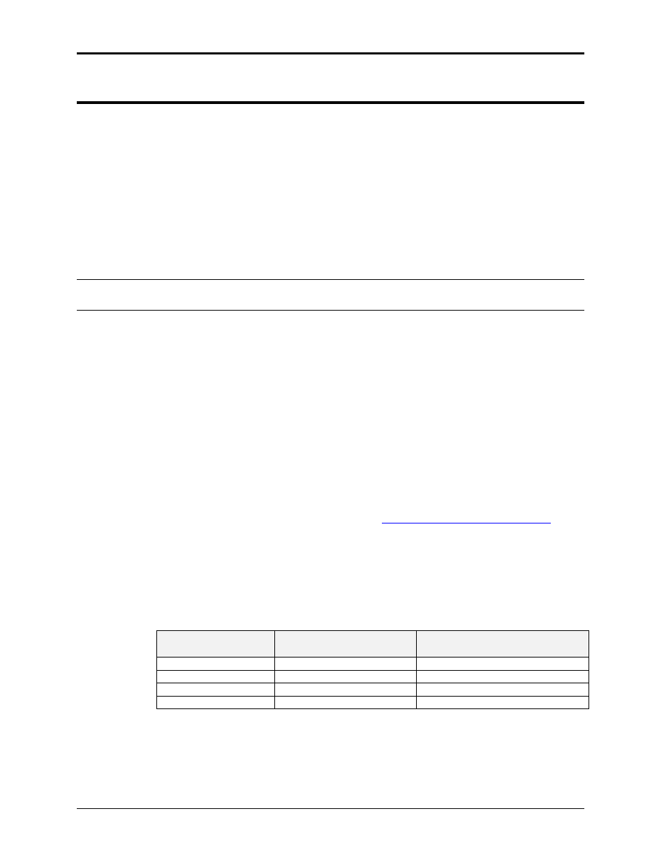
4. Check the amplifier gain balance by measuring the circulating current between
amplifiers. This current can be measured by monitoring the voltage at the test points
indicated in the table below on the current limit board. All test point measurements
are with respect to TP1 (common).
5. The voltage at each test point with no-load should be less than 20 millivolts. Make
any correction necessary by adjusting the Amplifier Gain on each amplifier. The gain
adjustment pot is indicated in the same table.
6. Check the balance at 50 Hz and again at the high frequency limit of the unit.
7. Contact AMETEK programmable power at
load balance exceeds 50 millivolts at the frequency extremes as the amplifier may
be defective in this case.
8. Repeat for Phase B and C and A, B and C amplifiers on the auxiliary unit(s). Use the
master unit‟s adjustment and test points for adjusting the master unit amplifiers and
the auxiliary unit‟s adjustment and test points for adjusting the auxiliary unit
amplifiers.
Output
Phase
Current Limit Board
Test Point
Adjustment Pot R104 on
Amplifier assembly:
A or 1
TP2
Phase A (A1)
B or 2
TP3
Phase B (A2
C or 3
TP4
Phase C (A3)
Common = TP1
Table 6-5: Amplifier balance adjustments